•
Disconnect the ribbon cable between the front cover and the CPU board (No. 1 in Figure 3-3 to
Figure 3-7) at the front cover side. Press the top latch of the plug connector up and the bottom latch
down so that the plug connector of the ribbon cable is pressed out. This action does not apply to the
device version with detached operator panel. However, on the central processor unit CPU (No. 1) the 7-
pole plug connector X16 behind the D-subminiture connector and the plug connector of the ribbon cable
(connected to the 68-pole plug connector on the rear side) must be removed.
•
Disconnect the ribbon cables between the CPU unit (No. 1) and the input/output printed circuit boards I/O
(No. 2), (No. 3) and (No. 4).
•
Remove the boards and set them on the grounded mat to protect them from ESD damage. In the case of
the device variant for panel surface mounting please be aware of the fact a certain amount of force is
required in order to remove the CPU board due to the existing plug connector.
•
Check the jumpers according to Figure 3-9 to Figure 3-19 and the following information. Change or
remove the jumpers if necessary.
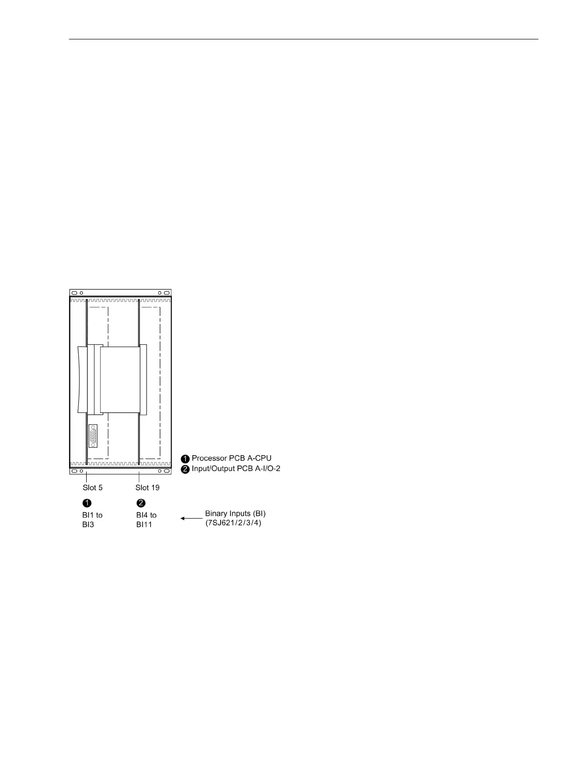
The arrangement of modules for device types and housing sizes are shown in Figure 3-3 to Figure 3-8.
Module Arrangement 7SJ62
The following figures show the arrangement of the modules for 7SJ62 in housing size
1
/
3
and housing size
1
/
2
.
[frontansicht-ohne-frontkappe7sj62-160502-wlk, 1, en_US]
Figure 3-3
Front view of housing size
1
/
3
after removal of the front cover (simplified and scaled down)
Mounting and Commissioning
3.1 Mounting and Connections
SIPROTEC 4, 7SJ62/64, Manual 373
C53000-G1140-C207-8, Edition 08.2016

 Loading...


