Installation and Commissioning
8-257SA6 Manual
C53000-G1176-C133-1
Input/Output Board
C–I/O–2
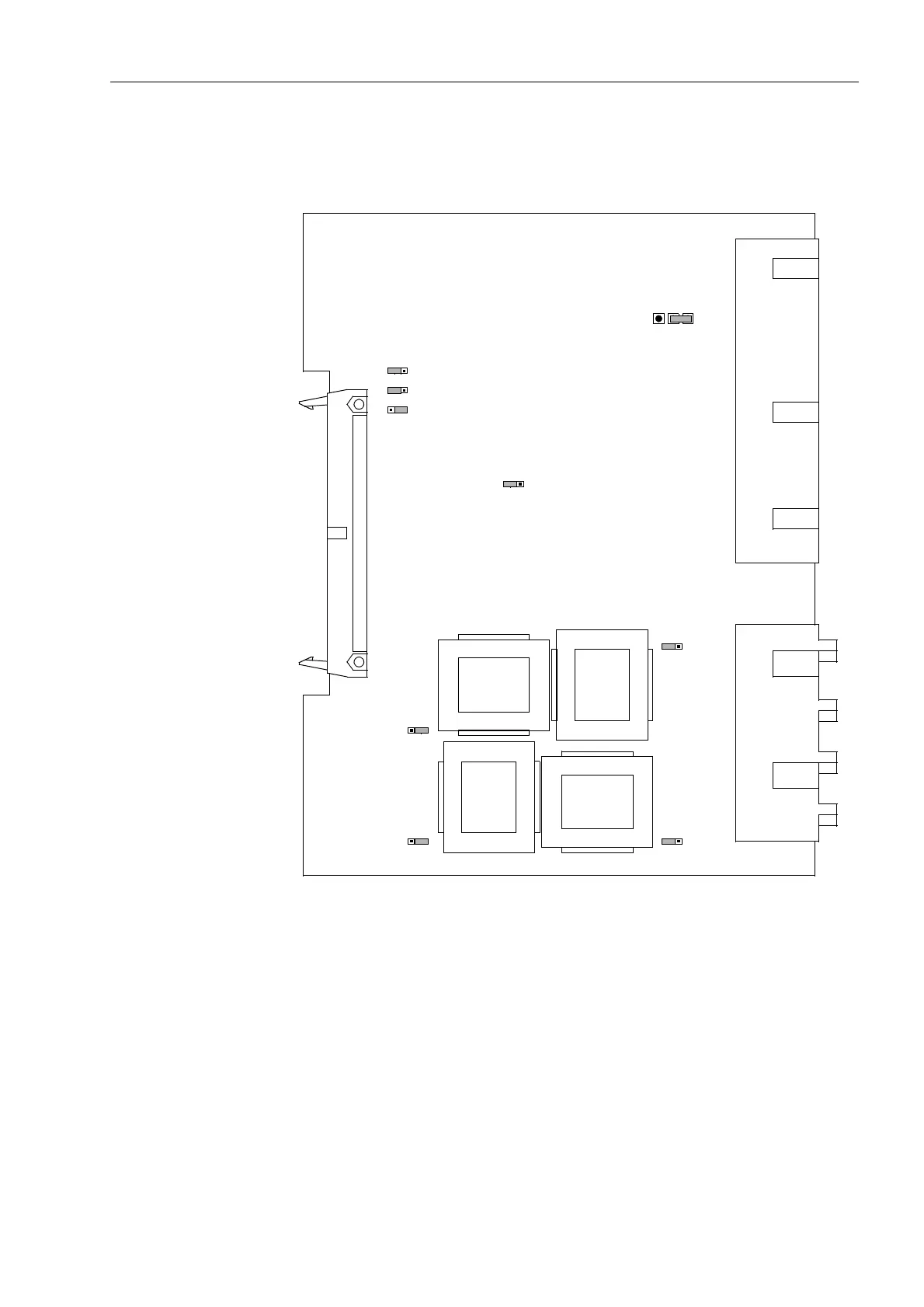
The layout of the printed circuit board for the input/output board C-I/O–2 is illustrated
in Figure 8-14.
Figure 8-14 The input/output board C-I/O–2 with the jumpers necessary for the setting
check
The contact of the relay for the binary output BO6 can be configured as NO or NC
contact (see also General Diagrams in Appendix A, Section A.2).
Mounting location:
for housing size
1
/
3
ê in Figure 8-8, slot 19,
for housing size
1
/
2
ê in Figure 8-9, slot 33,
for housing size
1
/
1
ê in Figure 8-10, slot 33 right.
X61
1A
5A
3
2
1
T8
T6
T7
T5
X64
1A
5A
3
2
1
X63
5A
1A
1
2
3
X62
5A
1A
1
2
3
X60
1A
5A
3
2
1
X41
1
3
2
(AD0)
L
X71
1
2
3
(AD1)
X72
1
2
3
(AD2)
X73
H

 Loading...


