100 Replacing boards and components
SIREMOBIL Iso-C SPR2-230.840.01.01.02 © Siemens, 2008
08.08 CS PS SP
Page 100 of 148
For internal use only
Removal 0
x Move the I.I. into the service position. See (I.I. service position / p. 25).
x Rotate the camera into the 0° position. See (Fig. 32 / p. 99).
VIDEOMED DC
x Cut off the cable ties (see arrow, (Fig. 32 / p. 99)) and disconnect the plugs.
x Remove plug X1 at the Compact optics.
x Remove the VIDEOMED DC and place it on a clean surface. See (Replacing the
VIDEOMED DC / p. 83).
High voltage section of the I.I. mini-voltage supply
x Remove the high voltage section of the I.I. mini-voltage supply. Remove both attach-
ment screws at the C-arm flange. See arrows, (Fig. 32 / p. 99).
x Disconnect the anode cable from the high voltage section.
x Remove the O-ring and the cap nut from the cable.
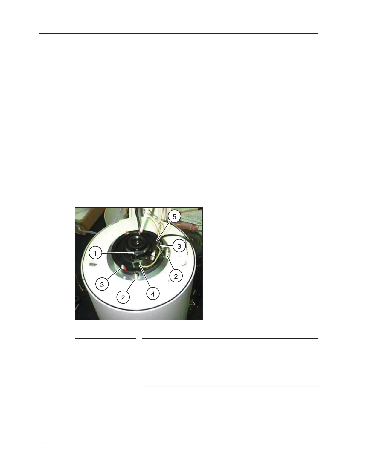
Compact optics
Fig. 33:
NOTE
When removing the Compact optics, make sure that no dust
or dirt particles contaminate the I.I. output.
Do not loosen the eccentric screws ((2/Fig. 33 / p. 100)) on
the edge of the Compact optics! These screws are used to
center the Compact optics to the I.I. output.
x Remove the attachment screws of the Compact optics. If necessary, remove the
retainer clip for the plug / cable leads as well.
x Remove the Compact optics.
 Loading...


