© Siemens, 2008 SPR2-230.840.01.01.02 SIREMOBIL Iso-C
08.08 CS PS SP
Replacing boards and components 125
Page 125 of 148
For internal use only
3D reconstruction system electronics 6.25
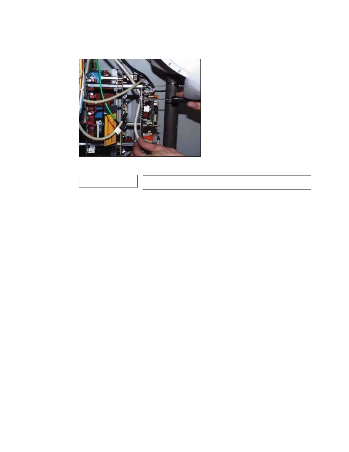
Fig. 39:
NOTE
Only applies to SIREMOBIL Iso-C 3D.
x The 3D reconstruction system electronics (PC boards D200 including MCB3 and D310)
is attached in front of PC board D1 in the basic unit ((Fig. 39 / p. 125)).
x Switch the system off.
x Unplug all connectors.
x Replace the module.
x Reconnect all connectors.
x Fasten the shielded cables in the shield connectors again, ensuring good ground con-
tact of the shielding.
x If cable ties have been removed, reattach the cables with cable ties.
x Perform a download of the control software as described in the Startup Instructions,
Chapter 5.
x Perform the mechanical settings as described in the Startup Instructions, Chapter 6.
x Perform chapters 10 and 11 of the IQ quick test.
 Loading...


