© Siemens, 2008 SPR2-230.840.01.01.02 SIREMOBIL Iso-C
08.08 CS PS SP
Replacing boards and components 121
Page 121 of 148
For internal use only
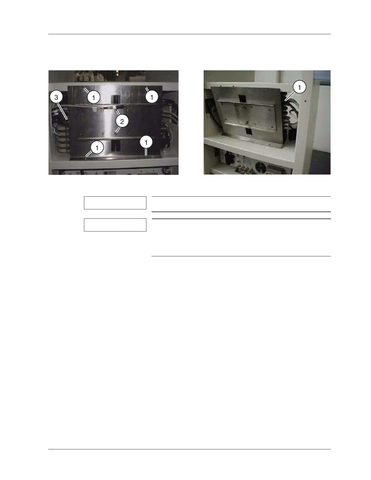
Video switcher 6.21
NOTE
Only applies to SIREMOBIL Iso-C 3D.
NOTE
Video switcher 1 ((3/Fig. 35 / p. 121)) is used to switch the
video signal between the MEMOSKOP and the 3D recon-
struction PC. Video switcher 2 ((1/Fig. 36 / p. 121)) is used to
route the video signal to the video printer.
x Switch the system off.
x Loosen the four fastening screws of the securing bracket ((1/Fig. 35 / p. 121)).
x Loosen the two clamping screws, but do not unscrew them completely
((2/Fig. 35 / p. 121)).
x Tip the holding plate with the video switchers into the monitor trolley compartment (see
(Fig. 36 / p. 121)).
x Unplug the connectors of the video switcher to be replaced.
x Pull the video switcher to be replaced out of the holding plate from the side.
x Press the green button on the video switcher.
x Push the new video switcher into the holding plate and reconnect all connectors.
x Screw the holding plate back onto the monitor trolley.
x Tighten the two clamping screws again.
x Switch the system on.
x After the system boots, the SIMOMED HM Monitor (reference monitor) should display
the MEMOSKOP reference image. If the boot process of the 3D reconstruction PC or
the syngo interface appears, the green button of video switcher 1 is in the wrong posi-
tion and needs to be switched over. ((3/Fig. 35 / p. 121)) points to video switcher 1.
x Perform the IQ quick test.
Fig. 35: Fig. 36:
 Loading...


