© Siemens, 2008 SPR2-230.840.01.01.02 SIREMOBIL Iso-C
08.08 CS PS SP
Prerequisites 15
Page 15 of 148
For internal use only
Notes on the protective conductor resistance test 0
Follow the instructions in the safety rules for installation and repair (ARTD-002.731.17...).
The protective conductor resistance must be measured after every intervention in the sys-
tem.
Documentation of the measured values is normally required only during periodic safety
checks.
If parts or components decisively influencing the protective conductor resistance are
replaced (e.g. power cable, power-up module, multicore connection cables that also create
the protective conductor connection between parts of the system, such as the monitor
cable or C-arm cable), or if protective conductor connections have been repaired, then the
protective conductor resistance must be measured, documented, and assessed.
The measurement must be made according to DIN VDE 0751, Part 1 (see ARTD Part 2).
In such cases, the protective conductor resistance to all conductive touchable parts of the
system must be measured.
Make sure not to mistake any control cables or data cables between the components of the
system for protective conductor connections.
During the measurement, the line power cable and additional connection cables that also
create the protective conductor connection between parts of the system (e.g. monitor cable
between basic unit and monitor cart) must be moved section by section to detect broken
conductors.
The protective conductor resistance must not exceed 0.2 ohms.
The values must be recorded and assessed as repeat measurements, and the measuring
points given, in the protective conductor resistance report.
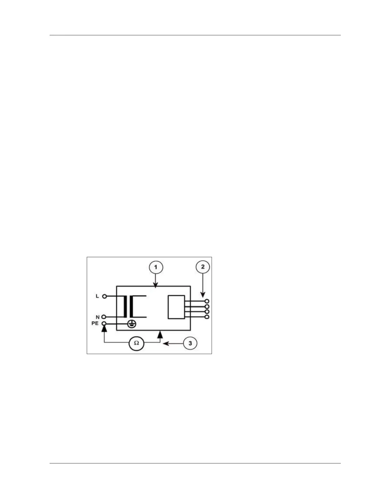
Fig. 2: Measuring circuit for the protective ground wire resistance for units that are disconnected
from power, in compliance with DIN VDE 0751-1:2001-10, Fig. C2
Pos. 1 System
Pos. 2 Applied part (if present)
Pos. 3 Measuring arrangement (integrated in measuring instrument)
 Loading...


