3-4
After entering the statement level you can work on the individual parts of a
Custom Control statement. The display shows the current statement on the top
line with the current “field” of the statement marked with focus brackets ( [ ] ).
The current option selection is shown in focus brackets on the lower line of the
display.
Use <▲> or <▼> to move between the statement fields on the top line and
<Next> and <Previous> to scroll through the options for the current field (and
display the new selection) on the lower line. Press <Enter> to move the new
option from the lower line to the selected field in the top line. This also moves
the field focus to the next field.
A total of 40 Custom Control equations are possible in the 4005. A Custom
Control equation consists of up to six statements. Each equation consists of two
sides: an INPUT SIDE and an OUTPUT SIDE. An equation can be better
understood as an “IF/THEN” command. “IF” the INPUT SIDE is true, “THEN”
execute the OUTPUT SIDE.
Each equation is made up of one or more input statement and one or more output
statement (for a total of six statements). The equation in Figure 3-4 has four
statements: two input statements and two output statements.
Equation
Input Statement
Input Statement
End of Inputs
Output Statement
Output Statement
End of Outputs
Figure 3-4. An Equation
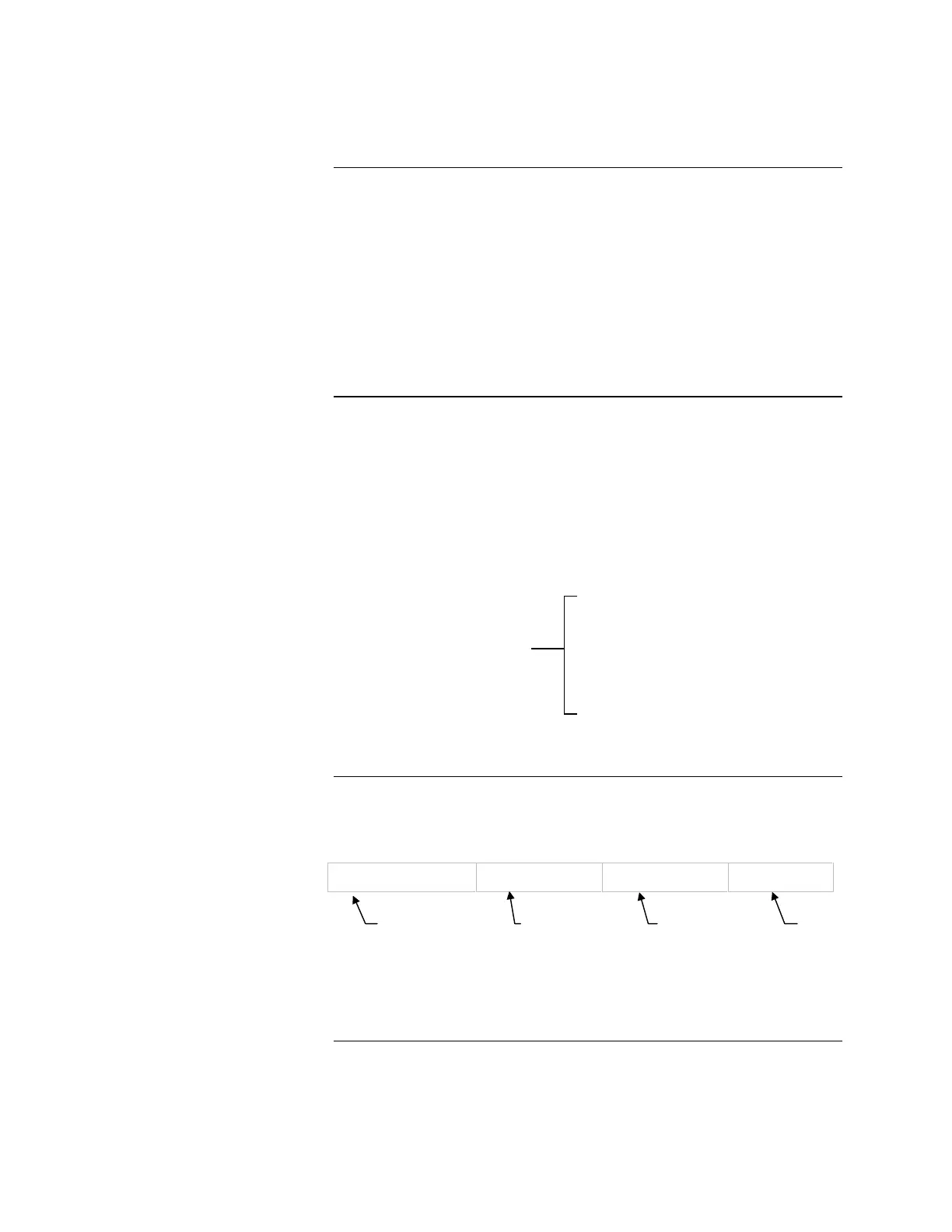
Each input statement is made up of four fields.
Field 1 Field 2 Field 3 Field 4
[] [127] [),5(] []
Figure 3-5. The Four Fields of an Input Statement
Continued on next page
Custom Control, Continued
Custom Control Level
Equations
Input Side (IF)
Empty field
starts a
Custom
Control
equation
Optional NOT
operator
Condition
qualifier for
field 4
Point
FIRST STATEMENT
Technical Manuals Online! - http://www.tech-man.com