2-1
This chapter discusses the basic programming functions that are available with
the 4005 Fire Alarm Control Panel (FACP). The programming of more advanced
functions is discussed in Chapter 3.
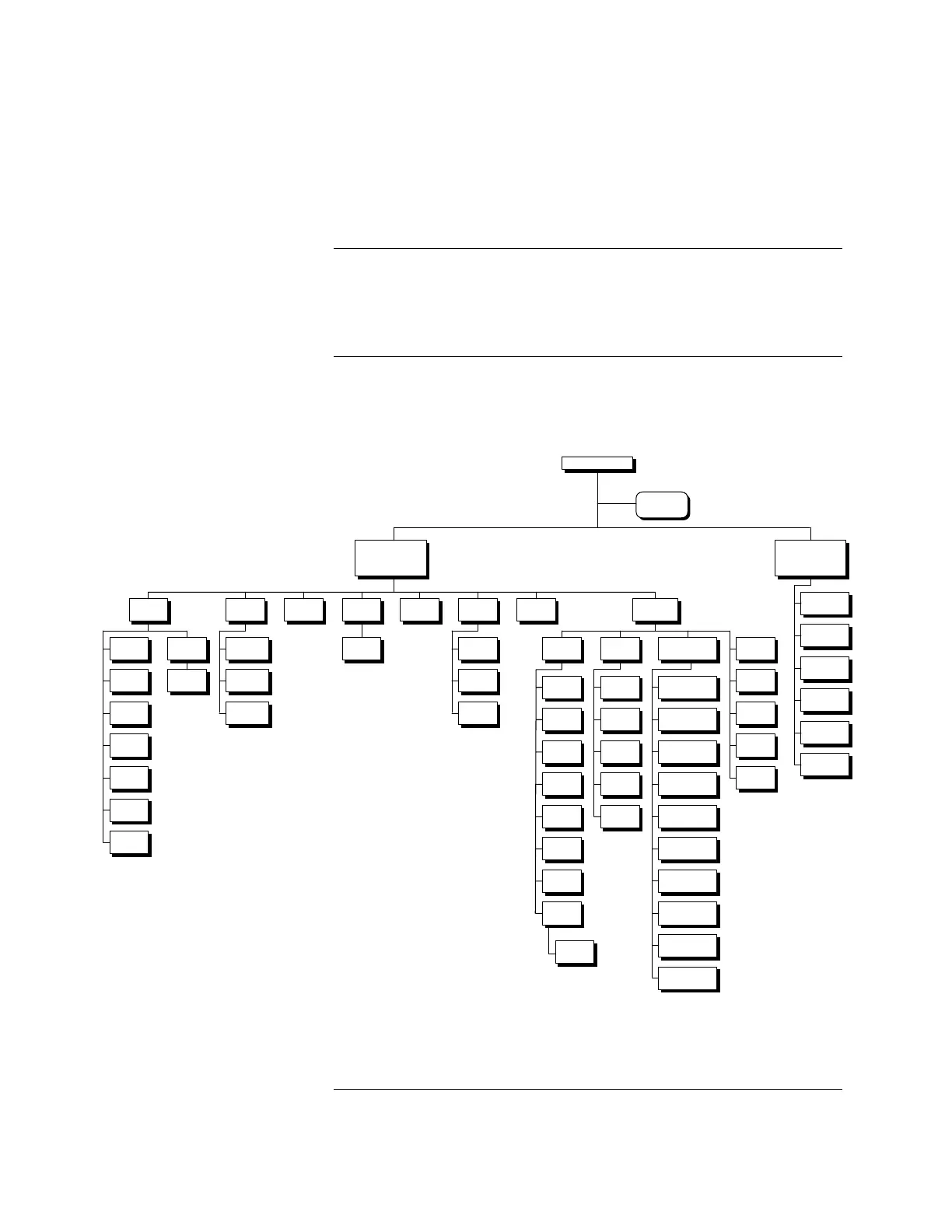
All programming is done from the front panel via menu-driven prompts. Access
levels protect different programming options. All programming described in this
publication assumes a Level 4 (Simplex Service Mode) access. Figure 2-1
illustrates the entire menu structure at Level 4 operation.
Figure 2-1. Level 4 Menu Structure
Continued on next page
Chapter 2
Basic Programming
Introduction
Menu Structure
View
Points
View
Points
Monitor
Monitor
Relay
Relay
Signal
Signal
Digit al
Digit al
Analog
Analog
List
List
Generic
Input
Generic
Input
Generic
Output
Generic
Output
System
Points
System
Points
History
Log
History
Log
Alarm Log
Alarm Log
Trouble Log
Trouble Log
Combine
Log
Combine
Log
Software
Revision
Software
Revision
Set
Time / Date
Set
Time / Date
Passcode
Passcode
Log In/Out
Log In/Out
Walk
Test
Walk
Test
Off
Off
Log
Log
Signal
Signal
Cold
Start
Cold
Start
Programming
Programming
Edit Point
Edit Point
Relay
Relay
Signal
Signal
Digital
Digital
Analog
Analog
List
List
Generic
Input
Generic
Input
Edit Card
Edit Card
System Options
System Options
Time / Date
Format
Time / Date
Format
Active Point
Reminder
Active Point
Reminder
Edit SMPL
Edit SMPL
Save CFIG
Save CFIG
Restore
CFIG
Restore
CFIG
Generic
Output
Generic
Output
Monitor
Monitor
Delete I/O
Card
Delete I/O
Card
Modify I/O
Card
Modify I/O
Card
Add RUI
Card
Add RUI
Card
Delete RUI
Card
Delete RUI
Card
Add I/O
Card
Add I/O
Card
Doorholder AC
Fail Drop Time
Doorholder AC
Fail Drop Time
Silence / Reset
Inhibit
Silence / Reset
Inhibit
Signal Operation
(Visible, Audible,
Evacuation)
Signal Operation
(Visible, Audible,
Evacuation)
Signal Cut-out
Time
Signal Cut-out
Time
Enable City
Circuit 1
Enable City
Circuit 1
Enable City
Circuit 2
Enable City
Circuit 2
Expansion Power
Supply
Expansion Power
Supply
Doorholder Alarm
Drop Timer
Doorholder Alarm
Drop Timer
Access
Level
Access
Level
Passcode
Passcode
Main Menu
activated from
MENU Key
Main Menu
activated from
MENU Key
Function Menu
activated from
FUNC Key
Function Menu
activated from
FUNC Key
City Circuit
Disconnect
City Circuit
Disconnect
Door Holder
Bypass
Door Holder
Bypass
Control Point
Bypass
Control Point
Bypass
Elevator
Bypass
Elevator
Bypass
Manual
Evacuation
Manual
Evacuation
Lamp Test
Lamp Test
TOP LEVEL
TOP LEVEL
High Level
Status Screen
High Level
Status Screen
Edit
Mode
Edit
Mode
Technical Manuals Online! - http://www.tech-man.com