Scope Multimeter Operation and Controls
92
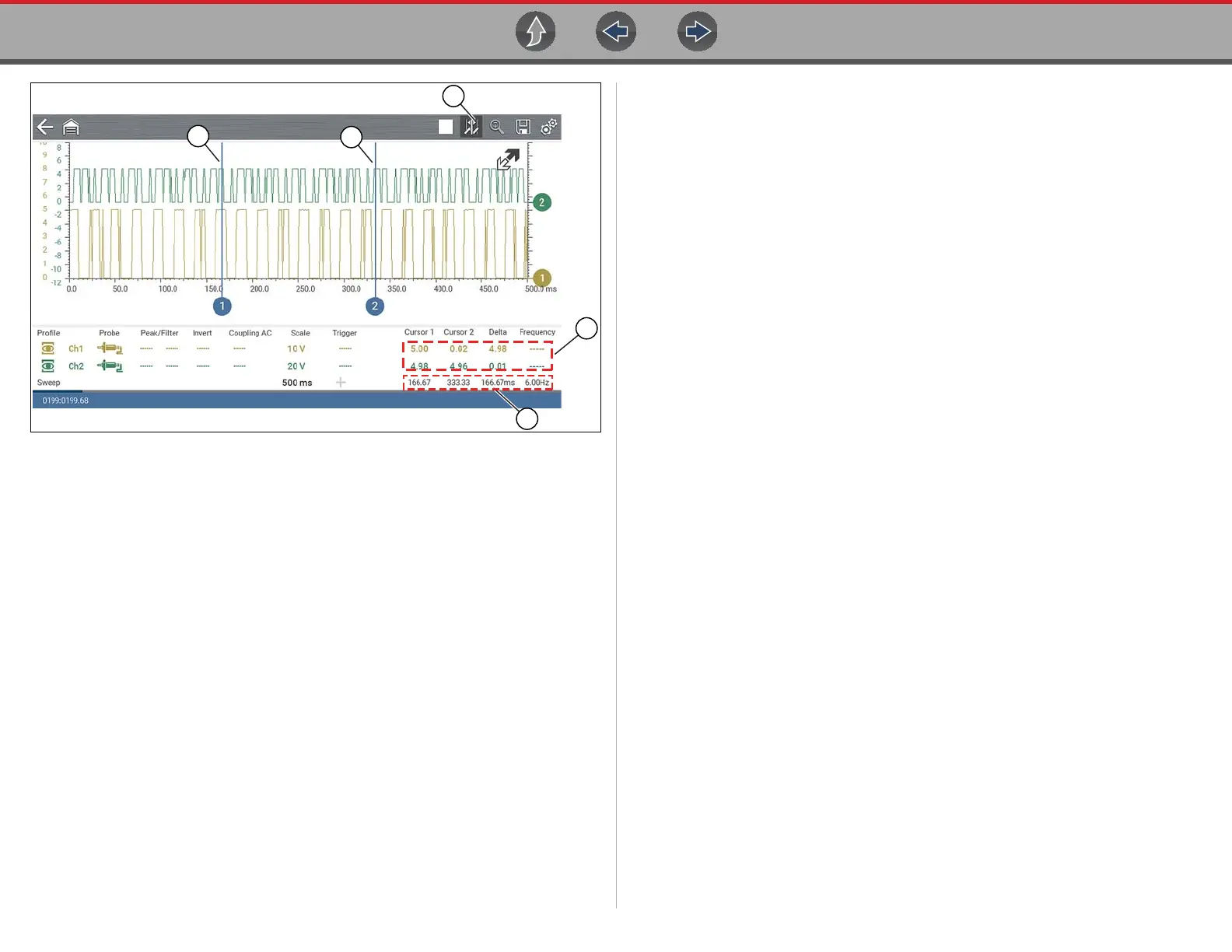
1— Cursors Icon
2— Cursor (no. 1)
3— Cursor Marker (no. 2)
4— Cursor Measurement Panel - amplitude and delta display
5— Cursor Measurement Panel - time and delta display
Figure 9-25
z To position the cursors:
The cursors can be positioned anywhere within the range of the sweep scale
(Figure 9-25).
1. Turn the Cursors on.
2. Using the touch screen, select either cursor marker (base) and drag it to the
desired position.
Cursor Measurements Panel
When the cursors are turned on, the Refresh, Min, Live, Max display panel is
switched off and replaced by the Cursor Measurements Panel.
The cursor measurements panel displays the following signal and cursor
measurements:
• Signal amplitude at two points
• Signal amplitude difference (delta) between two points
• Cursor position in time at two points
• Difference (delta) in time between the cursors
• Frequency - frequency of the signal for the time period between cursor 1 and 2
The cursor measurements panel contains values for each channel in two displays.
The amplitude and delta display is provided in the channel specific color and
includes:
– Cursor 1 - signal amplitude at cursor 1 position
– Cursor 2 - signal amplitude at cursor 2 position
– Delta - signal amplitude difference between cursor 1 and 2
The time and delta display is gray in color and includes:
– Cursor 1 - cursor position in time at cursor 1
– Cursor 2 - cursor position in time at cursor 2
– Delta - difference in time between cursor 1 and 2
– Frequency - the frequency value (Hz) of the signal for the time period
between cursor 1 and 2
5

 Loading...