S2 User Handbook
97
14
S2ODPF/S2ODP DIGITAL OUTPUT PGM CHANNEL
WITH & WITHOUT MASTER FADER VERSION 1
S2ODPF/S2ODP DIGITAL OUTPUT
PGM CHANNEL WITH & WITHOUT
MASTER FADER VERSION 1
Summary of Jumper Settings for the PGM Digital Output Channel
Jumper
Set over
Pins
Eect
J1
1 & 2
None
Cleanfeed 1 terminated.
Cleanfeed 1 active.
J2
1 & 2
None
Cleanfeed 2 terminated.
Cleanfeed 2 active.
J3-J6 See table (page 96) Synchronisation Mode & Sample Rate Selection.
J7-J8 See table (page 96) Output Bit Depth Selection.
J9 See table (page 96) Channel Status Bits Selection.
J10
1 & 2
2 & 3
AES/EBU sync input selected.
S/PDIF sync input selected.
J11 1 & 2 AES/EBU sync input selected.
2 & 3 S/PDIF sync input selected.
J12 1 & 2 S/PDIF output selected.
2 & 3 AES/EBU output selected.
Note: Options in bold are set as default when shipped.
P5
A/D
Trim L
A/D
Trim R
P6
P6
P8
P9
P7
LK42
Module A
LK45
Digi
Left
Lim
Sym.
Right
Lim
Sym.
Set
Threshold
Set
Gain
J11J10
J12
J1J2
J3
J4
J5
J6
J7
J8
J9
AES
SPDIF
AES
SPDIF
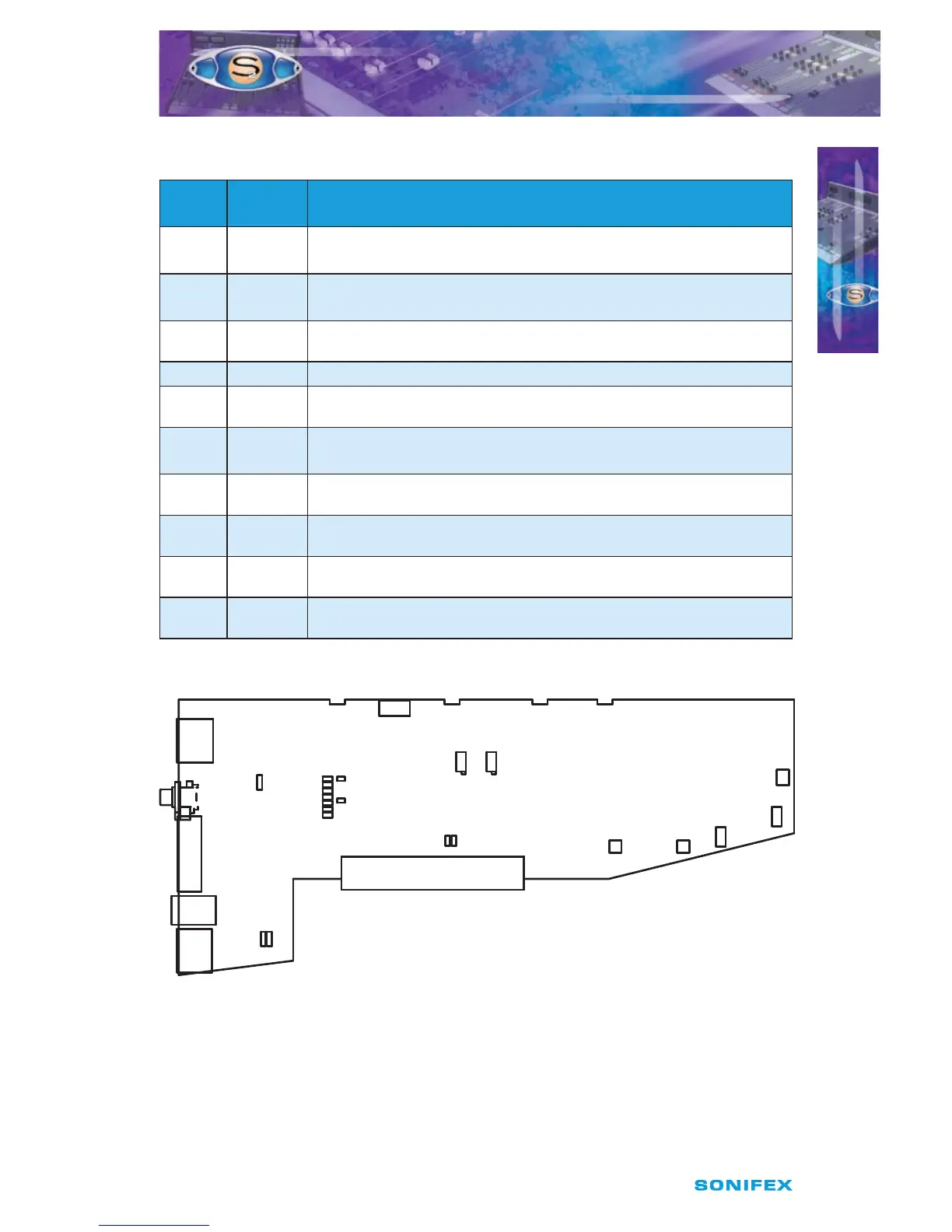
Fig 14-1 : S2 Digital PGM Output Board Layout.