102
S2 User Handbook
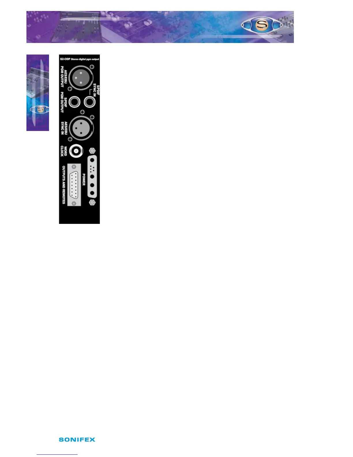
Rear Panel
AES/EBU PGM Output Connector
This XLR 3 pin plug is used for the AES/EBU Output, and has the following
connections;
Pin 1: Screen.
Pin 2: Phase.
Pin 3: Non-phase.
S/PDIF PGM Output Connector
This phono connector is used for S/PDIF output. There are on board
jumpers to set up this input in place of the AES/EBU output.
Inner: Signal.
Outer: Screen.
S/PDIF Sync Input Connector
This phono connector is used for the S/PDIF sync input. There is an on
board jumper to set up this input in place of the AES/EBU sync input.
Inner: Signal.
Outer: Screen.
Outputs & Remotes Connector
This 15 pin D type socket provides outputs for the following channel
functions;
t 1(.BOBMPHVFPVUQVUT
t .POPBOBMPHVFPVUQVU
t $POUSPM3PPNNVUJOHSFMBZT5IFNVUFSFMBZJTBEPVCMFQPMFSFMBZ
2A at 30VDC max
The connector pin-out is as follows;
Pin 1: Chassis ground.
Pin 2: PGM left output phase.
Pin 3: PGM right output phase.
Pin 4: No connection.
Pin 5: No connection.
Pin 6: Mono output phase.
Pin 7: Control Room mute relay contact 1A (makes to pin 14).
Pin 8: Control Room mute relay contact 2A (makes to pin 15).
Pin 9: PGM left output non-phase.
Pin 10: PGM right output non-phase.
Pin 11: No connection.
Pin 12: No connection.
Pin 13: Mono output non-phase.
Pin 14: Control Room mute relay contact 1B.
Pin 15: Control Room mute relay contact 2B.
15
S2ODPF/S2ODP DIGITAL OUTPUT
PGM CHANNEL WITH & WITHOUT
MASTER FADER VERSION2
S2ODPF/S2ODP DIGITAL OUTPUT PGM CHANNEL
WITH & WITHOUT MASTER FADER VERSION 2