64
S2 User Handbook
Summary of Jumper Settings for the Digital Dual Stereo Channel With & Without EQ
Jumper Set over Pins Eect
J1
1 & 2
None
Latching contact for Line 1 remote start.
Momentary contact for Line 1 remote start.
J2
1 & 2
None
Latching contact for Line 2 remote start.
Momentary contact for Line 2 remote start.
J3
1 & 2
None
Continuous momentary start from ON button,
see following description.
Normal start function.
J4
1 & 2
None
Fader up signal cancels previously selected CUE/PFL.
Normal CUE/PFL function.
J5
1 & 2
None
De-emphasis at 50/15μs, enabled.
De-emphasis disabled.
J6
1 & 2
2 & 3
None
Auto start Timer 1.
Auto start Timer 2.
No timer function.
J7
1 & 2
2 & 3
Input 1 selected from AES/EBU.
Input 1 selected from S/PDIF.
J8
1 & 2
2 & 3
Input 2 selected from AES/EBU.
Input 2 selected from S/PDIF.
J9 Not Fitted
J10 Not Fitted
J11
1 & 2
None
PFL is disabled when no digital input is detected
Normal PFL function
J12
1&2
None
Bal/Pan control is a Pan control
Bal/Pan control is a Balance control
J13
1&2
None
Bal/Pan control is a Pan control
Bal/Pan control is a Balance control
Note: Options in bold are set as default when shipped.
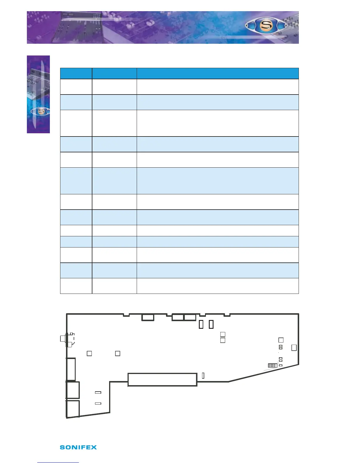
Fig 9-1 : S2 Digital Dual Stereo Input Board Layout.
P15
P16
P15 =
Left Sym.
P16 =
Right Sym.
Jumper Options
J1 = Latch Start I/P 1
J2 = Latch Start I/P 2
J3 = Cont. Mom. Start
from On Button
J4 = Fader Cancel Cue/PFL
J5 = De-emphasis
J6A = Timer 1 B = Timer 2
J11 = Unlocked PFL Mute
J6
P17
Set VCA 0dB
Dual Stereo
Dual Stereo with EQ
J1-J5
LK4
J11
LK5
LK9
LK10
LK12
I/P 1
Trim L
P1
I/P 1
Trim R
P2
A
B
Jumper
Options
Jumpers J7 &J8
Pos. A = AES
Pos. B = SPDIF
Digital
J7
Input 1
B A
J8
Input 2
B A
J13 J12
S2CDSE/S2CDS DIGITAL DUAL
STEREO LINE CHANNEL WITH &
WITHOUT EQ
S2CDSE/S2CDS DIGITAL DUAL STEREO
LINE CHANNEL WITH & WITHOUT EQ
9