84
S2 User Handbook
S2-CSMM STEREO MIX MINUS CHANNEL WITH EQ
12
The outputs on the this channel can also be congured by jumper settings as a mono sum
of mix-minus on the left channel and continuous talkback on the right channel (for use with
some ISDN codec applications and telephone balance units).
Fader
The 100mm VCA fader provides unity gain when fully open. The channel input signal is
routed to the outputs whenever the fader is open, the ON button is selected and either or
both of the routing buttons are selected.
ON Selection
The ON button works in conjunction with the fader and is used to control channel remotes,
routing, timers, etc. The button shows various states. When unlit the channel is o. Flashing
red indicates that the channel has been selected to ON but remains unrouted i.e. neither
PGM or AUD is selected. Steady red indicates that the channel is ON and “armed”, ready
for the fader to be raised. Raising the fader changes the illumination to green indicating
that the channel is live. Alternatively, with the button unlit the fader may be raised and
the channel can be operated simply by selecting ON. The illumination in this case toggles
between unlit, channel OFF and green, channel ON. Remotes, etc, are triggered when the
fader is up and the channel ON button shows green.
Scribble Pad
A scribble pad is provided at the bottom for user labelling of the channel function
e.g. “OB 1”.
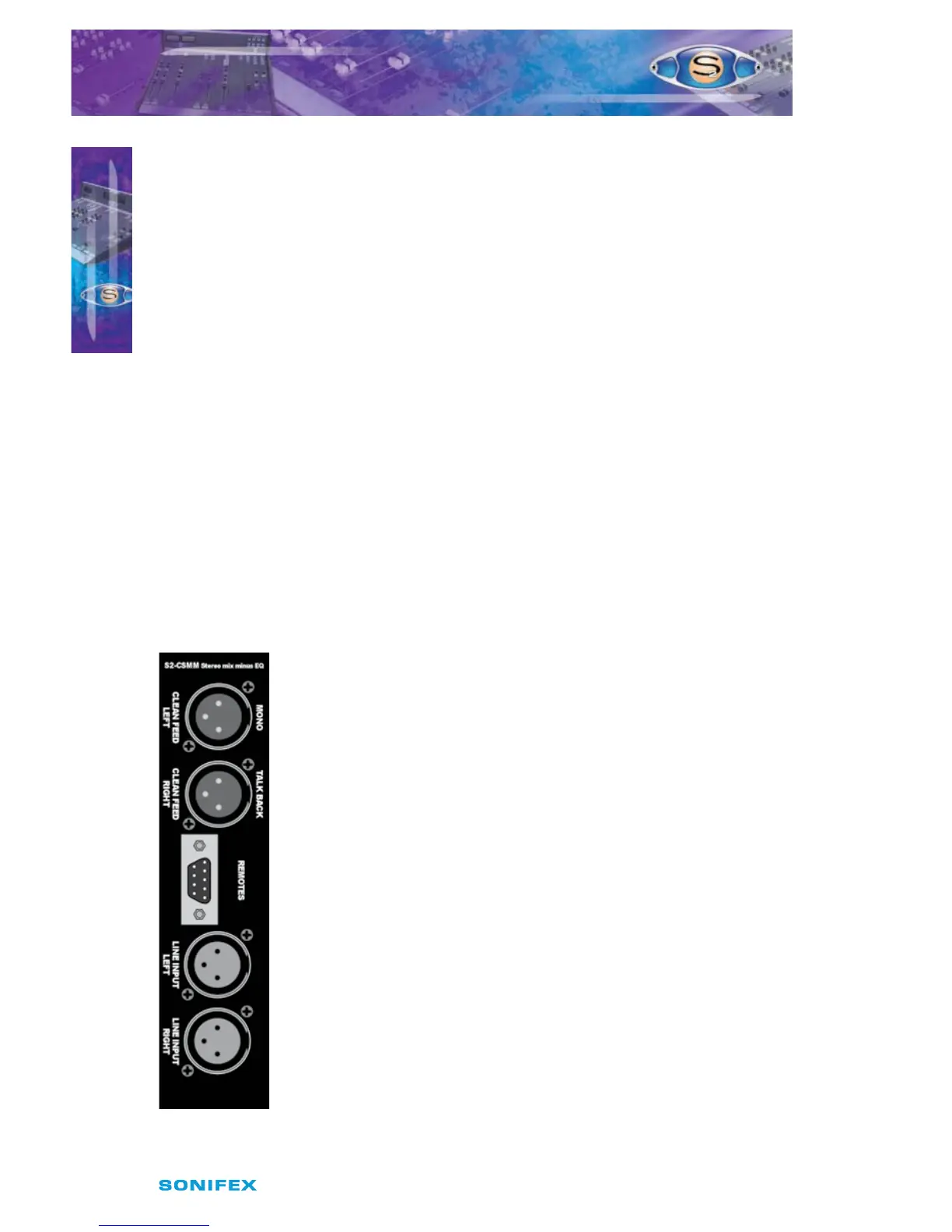
Rear Panel
Left Cleanfeed Output Connector
This XLR 3 pin plug is used for the left channel cleanfeed output, and has
the following connections;
Pin 1: Screen.
Pin 2: Phase.
Pin 3: Non-phase.
Right Cleanfeed Output Connector
This XLR 3 pin plug is used for the right channel cleanfeed output, and
has the following connections;
Pin 1: Screen.
Pin 2: Phase.
Pin 3: Non-phase.
Remotes Connector
This 9 pin D type plug provides inputs and outputs for the following
channel functions;
t -JOFJOQVUSFNPUFTUBSU
t -JOFJOQVUSFNPUFTUPQ
S2-CSMM STEREO MIX MINUS
CHANNEL WITH EQ