22
S2 User Handbook
Resetting the S2-PSU States
The S2-PSUS detects when a power supply has been removed or unplugged. If this occurs,
the S2-PSUS assumes the power supply has been serviced and all failure statistics are
refreshed. If a rail has failed permanently, removing or unplugging the supply will allow the
rail to be fully tested again, once reinstated. Removing both power supplies will reset the
S2-PSUS, indicated by the alternating front led sequence.
Usage Advice
The unit has been designed to give the user as little down time as possible. If an S2-PSU
rail reaches an unrecoverable state, please remove and service it. If an extreme fault occurs
(total loss of power) on the +VD rail, the switch over can cause a reset of digital modules
which will result in a small audio glitch.
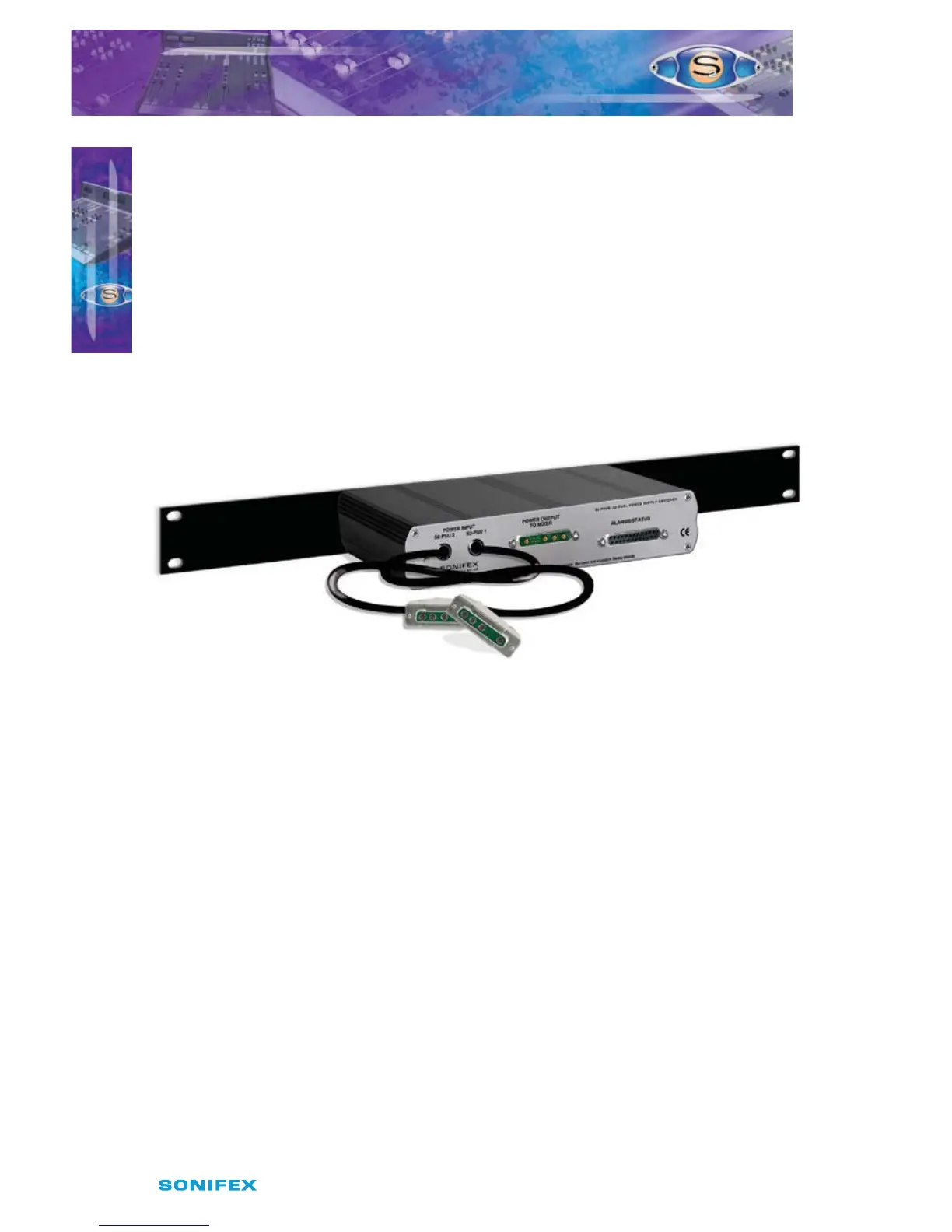
Rear Panel
Fig 3-6: S2-PSUS Rear Panel.
There are alarm outputs on the rear of the unit, created using opto-isolator switches.
These alarm outputs mimic those on the front panel and there is also an alarm relay which
operates as a warning for total unit failure. This will come on if the both power supplies
have failed.
Power Input Connectors
Two trailing leads 0.5m in length are used to connect 2 x S2-PSU units to the power switcher.
Power Output Connector
This 9 pin D type connector (see Fig 2-9) is used to route power to the Mixer from either the
master or slave power supply. It has the same connections as the output from the PSU (see
above).
Alarm & Status Connector
This 25 pin D type socket provides alarm and status output for the power switcher and has
the following connections;
Pin 1: 0V.
Pin 2: Opto isolated +VE master alarm NPN collector.
Pin 3: Opto isolated +VE master alarm NPN emitter.
Pin 4: Opto isolated +VE slave alarm NPN collector.
POWER SUPPLY
POWER SUPPLY
3