118
S2 User Handbook
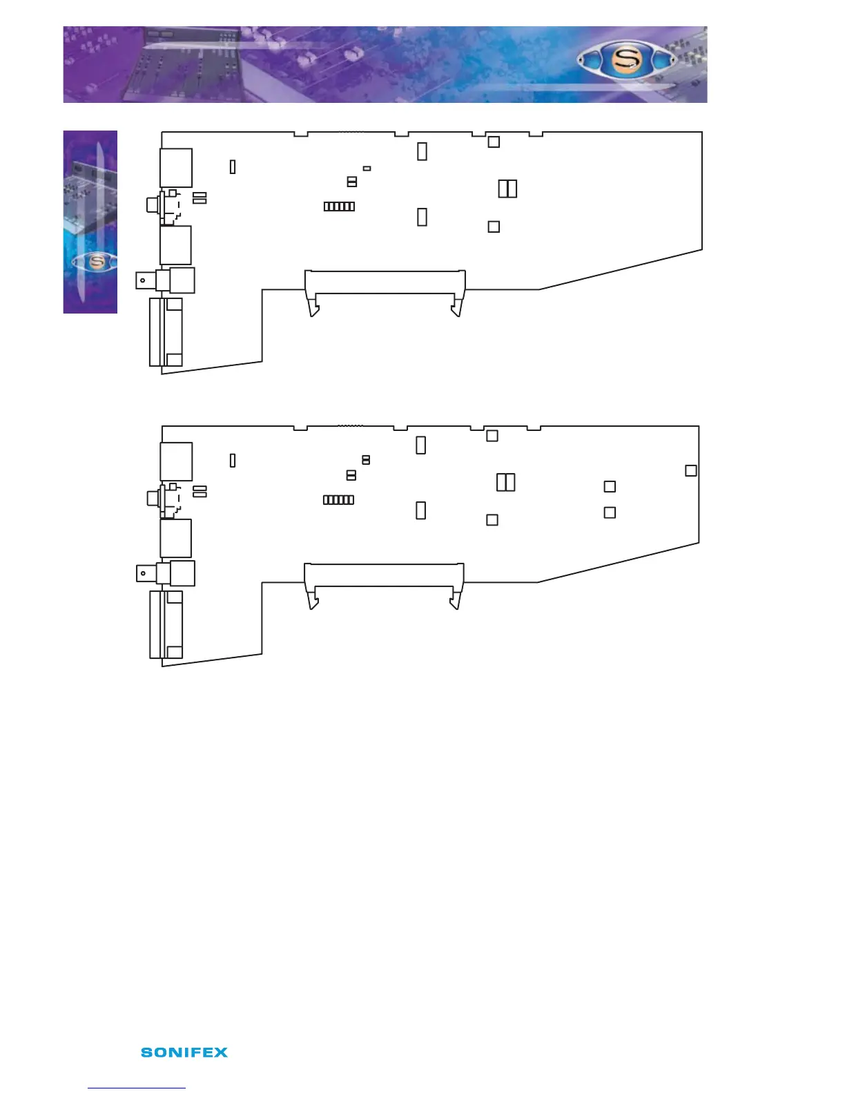
Fig 17-1 : S2 Digital AUD Output Board Layout.
Fig 17-2 : S2 Digital AUD Output With Fader Board Layout.
Synchronisation Mode and Sample Rate
The following jumpers, J3 to J6 and J9 on V2, are used for setting the Sync Mode and Sample
Rate of the digital output.
In Master mode, the digital output sample rate is simply set by, and locked to, the internal
on-board clock generator. No sync signal is used or required.
In Auto mode the sample rate follows the sync input. When the sync signal is not present
the sample rate will be set by, and locked to, the internal on-board clock generator at a
frequency determined by the jumpers.
In Auto Lock mode, the sample rate follows the sync input. If the sync signal is removed then
the sample rate will be set by, and locked to, the internal on-board clock generator at the
closest frequency available to the previous sync input. When there has been no sync input
detected the output will lock to the on-board clock generator at 32kHz.
S2ODAF/S2ODA DIGITAL OUTPUT AUD CHANNEL
WITH & WITHOUT MASTER FADER VERSION 2
S2ODAF/S2ODA DIGITAL OUTPUT
AUD CHANNEL WITH & WITHOUT
MASTER FADER VERSION 2
17
J12
AES
SPDIF
AES
SPDIF
J11
J10
J3J5 J7
J4J6 J8
J13
LK43
J9
Audition
P4
P5
P6
P8
P9
P7
Set ThresholdSet Gain
Right Lim
SYM
Left Lim
SYM
J12
AES
SPDIF
AES
SPDIF
J10
J11
J3J5 J7
J4J6 J8
J13
LK43
J9
Audition
LK46
Fader
P4
P5
P6
P8
P9
P7
Set ThresholdSet Gain
Right Lim
SYM
Left Lim
SYM
Right SYM
Left SYM
P2
P1
P3
Set VCA
0dB