40
S2 User Handbook
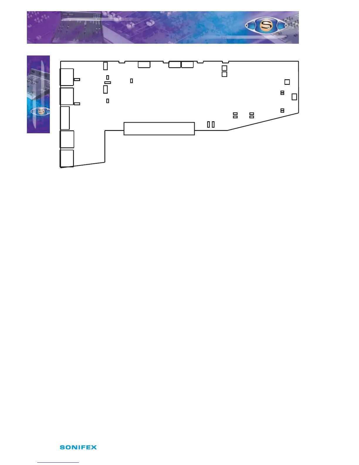
Fig 6-1 : S2 Mic/Mic Input Board Layout.
Remote for Mic 1 Cue Light
The remote output for the Microphone 1 input can be used to operate a Mic Cue light when
the channel is ON and the fader is up. This should not be confused with a Mic Live light.
The Mic Cue light is used for indicating to presenter or guest that they should talk into the
microphone. Jumper J1 is placed over pins 1 & 2. This is the default setting and produces a
latched remote output.
Remote for Mic 2 Cue Light
The remote output for the Microphone 2 input can be used to operate a Mic Cue light when
the channel is ON and the fader is up. This should not be confused with a Mic Live light.
The Mic Cue light is used for indicating to presenter or guest that they should talk into the
microphone. Jumper J2 is placed over pins 1 & 2. This is the default setting and produces a
latched remote output.
CUE/PFL Cancel
The CUE/PFL function is normally an alternate action. Press the button to select and press
again to de-select. However it may be desirable to have the fader up signal cancel a CUE/
PFL selection. Placing a jumper over J4 pins 1 & 2 will enable a previously selected CUE/PFL
function to be cancelled when the fader is up and the channel is ON. The default setting is
none (not tted).
Phantom Power Mic 1
If you will be using a phantom powered microphone, jumper J6 must be placed over pins 1
& 2. If a normal microphone is used the jumper should be left over pins 2 & 3. With phantom
power selected a voltage of +48V is applied to pins 2 & 3 of the XLR connector. The voltage
is applied through 6k8 resistors limiting the current to 14mA. The default setting is with the
jumper over pins 2 & 3.
Mic 1 LF Response
The default setting of J7 is with the jumper over pins 1 & 2 which gives a full LF response to
the microphone. However, if your studio is acoustically poor and suers from a lot of low
S2CMM MIC/MIC CHANNEL WITH EQ
S2CMM MIC/MIC CHANNEL WITH EQ
6
J6
Mic