98
S2 User Handbook
14
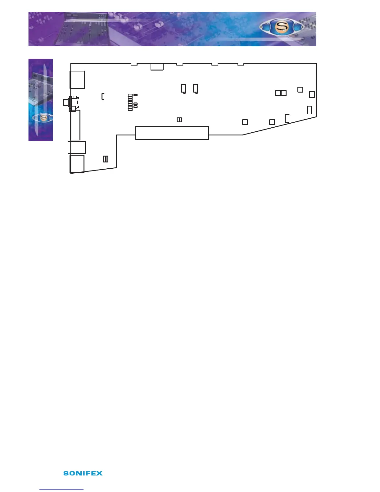
Fig 14-2 : S2 Digital PGM Output With Fader Board Layout.
Cleanfeed Terminations
If the console is supplied without Telco channels then J1 and J2 will be tted to terminate
the cleanfeed mix busses. With one Telco channel only J2 is tted and with two Telco
channels no jumpers are tted. There is no default setting.
Synchronisation Mode and Sample Rate
The following jumpers, J3 to J9, are used for setting the Sync Mode and Sample Rate of the
digital output.
In Master mode, the digital output sample rate is simply set by, and locked to, the internal
on-board clock generator. No sync signal is used or required.
In Auto mode the sample rate follows the sync input. When the sync signal is not present
the sample rate will be set by, and locked to, the internal on-board clock generator at a
frequency determined by the jumpers.
In Auto Lock mode, the sample rate follows the sync input. If the sync signal is removed then
the sample rate will be set by, and locked to, the internal on-board clock generator at the
closest frequency available to the previous sync input. When there has been no sync input
detected the output will lock to the on-board clock generator at 32kHz.
In Slave mode, the sample rate follows the sync input. When the sync signal is not present
the digital output is muted.
P5
A/D
Trim L
A/D
Trim R
P6
P6
P8
P9
P7
P2 P1
P3
Set VCA
0dB
LK42
LK46
Module A
LK45
Digi
Fader
Left
Lim
Sym.
Right
Lim
Sym.
Set
Threshold
Set
Gain
Right
Sym.
Left
Sym.
J11J10
J12
J1J2
J3
J4
J5
J6
J7
J8
J9
AES
SPDIF
AES
SPDIF
S2ODPF/S2ODP DIGITAL OUTPUT PGM CHANNEL
WITH & WITHOUT MASTER FADER VERSION 1
S2ODPF/S2ODP DIGITAL OUTPUT
PGM CHANNEL WITH & WITHOUT
MASTER FADER VERSION 1