124
S2 User Handbook
18
Channel Options and Jumper Settings
The control room monitor channel can be congured in a number of dierent ways
depending on the jumper options set on the board. The on-board processor’s software is
congured by jumpers J1 to J4 and channel identifying links. The control room monitor is
identied by having link LK10 tted.
The standard options available are;
t &OBCMFEJTBCMFHMPCBMUBMLCBDL
t &OBCMFEJTBCMFUBMLCBDLUPMPVETQFBLFST
t &OBCMFEJTBCMFUBMLCBDLEJNNJOHPOMPVETQFBLFST
t &OBCMFEJTBCMFUBMLCBDLEJNNJOHPOIFBEQIPOFT
Summary of Jumper Settings for the Control Room Monitor Channel
Jumper Set over Pins Eect
J1
1 & 2
None
Global talkback enabled.
Global talkback disabled.
J2
1 & 2
None
Control Room Loudspeaker talkback enabled.
Control Room Loudspeaker talkback disabled.
J3
1 & 2
None
Control Room Loudspeaker talkback dimming enabled.
Control Room Loudspeaker talkback dimming disabled.
J4
1 & 2
None
Control Room Headphones talkback dimming enabled.
Control Room Headphones talkback dimming disabled.
Note: Options in bold are set as default when shipped.
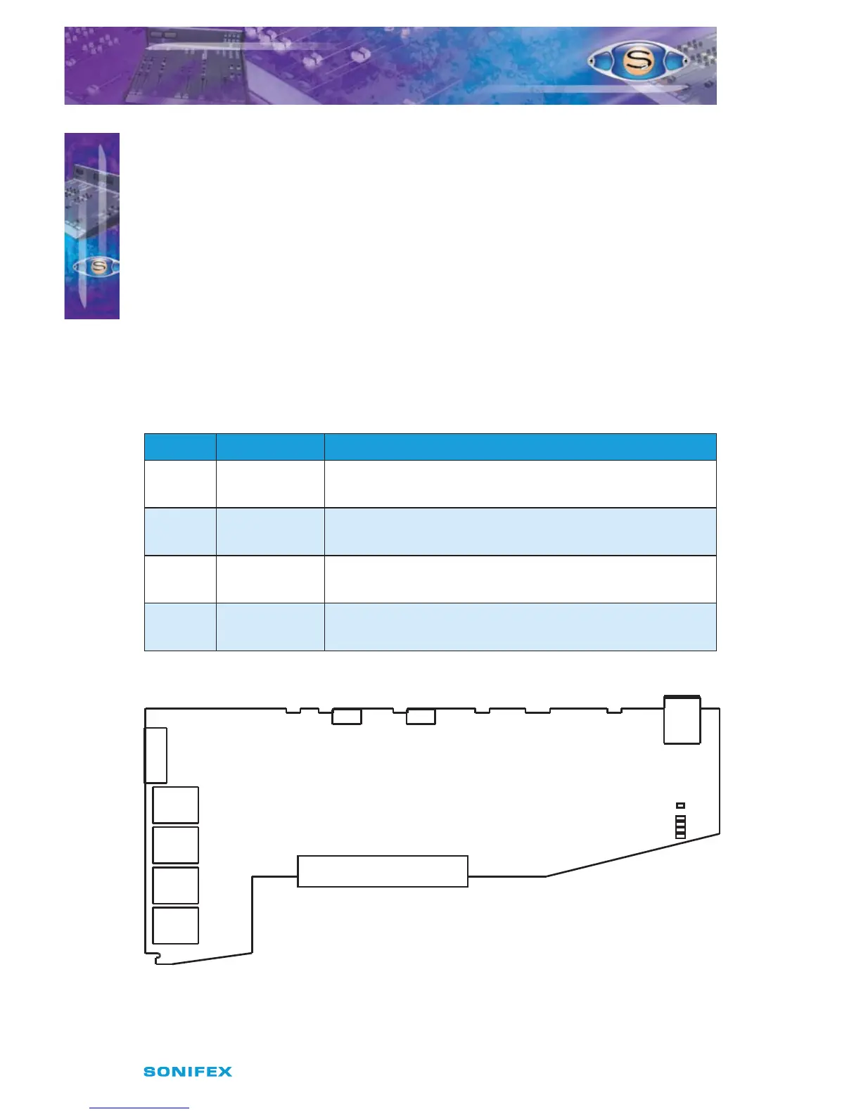
Fig 18-1 : Control Room Monitor Board Layout.
S2OMC CONTROL ROOM
MONITOR CHANNEL
S2OMC CONTROL ROOM MONITOR CHANNEL
J3
J4
J2
LK10
C/Room
J1
Jumper Options
J1 = Global T/B Enable
J2 = LS T/B Enable
J3 = LS Dim Enable
J4 = HP Dim Enable