144
S2 User Handbook
METERBRIDGE MODULES
20
METERBRIDGE MODULES
Pin 17: Input 2 right non-phase.
Pin 18: Input 3 left non-phase.
Pin 19: Input 3 right non-phase.
Pin 20: Input 4 left non-phase.
Pin 21: Input 4 right non-phase.
Pin 22: Input 5 left non-phase.
Pin 23: Input 5 right non-phase.
Pin 24: Input 6 left non-phase.
Pin 25: Input 6 right non-phase.
Audio Output Connector (To Mixer) - 9 pin D-type male (plug)
Pin 1: Screen.
Pin 2: Out left phase.
Pin 3: Out right phase.
Pin 4: No connection.
Pin 5: No connection.
Pin 6: Out left non-phase.
Pin 7: Out right non-phase.
Pin 8: No connection.
Pin 9: No connection.
Power Connectors
Pin 1: +VD.
Pin 2: Ground.
Pin 3: +15V.
Pin 4: -15V.
There are two power connectors on the board, a ‘power input’ and a ‘power through’
connector. The power input connector should be connected to the meterbridge distribution
board power connector, or the ‘power through’ connector on another meterbridge panel.
The ‘power through’ connector can be used to daisy chain power down the meterbridge
housing, for example, to an S2-MT panel.
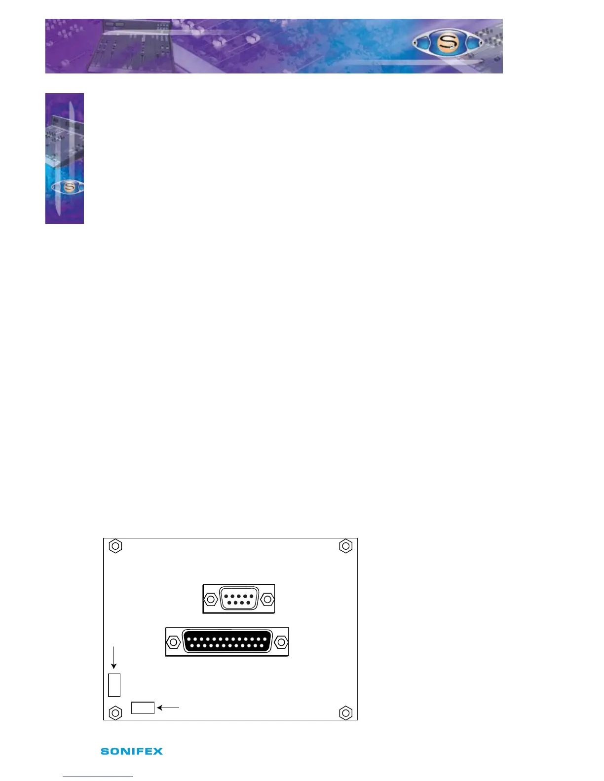
Fig 20-10b : S2-M6SS Diagram.
Audio Output on 9 Way D-type Plug
Audio Inputs on 25 Way D-type Socket
Power Through Connector to
S2-MT Timer Panel (if fitted)
Power Input Connector.
Power from Meterbridge
Distribution Board
‘Timer’ output
(see Fig 20-1)