6
S2 User Handbook
The main types of connectors used with the S2 mixers are the following:
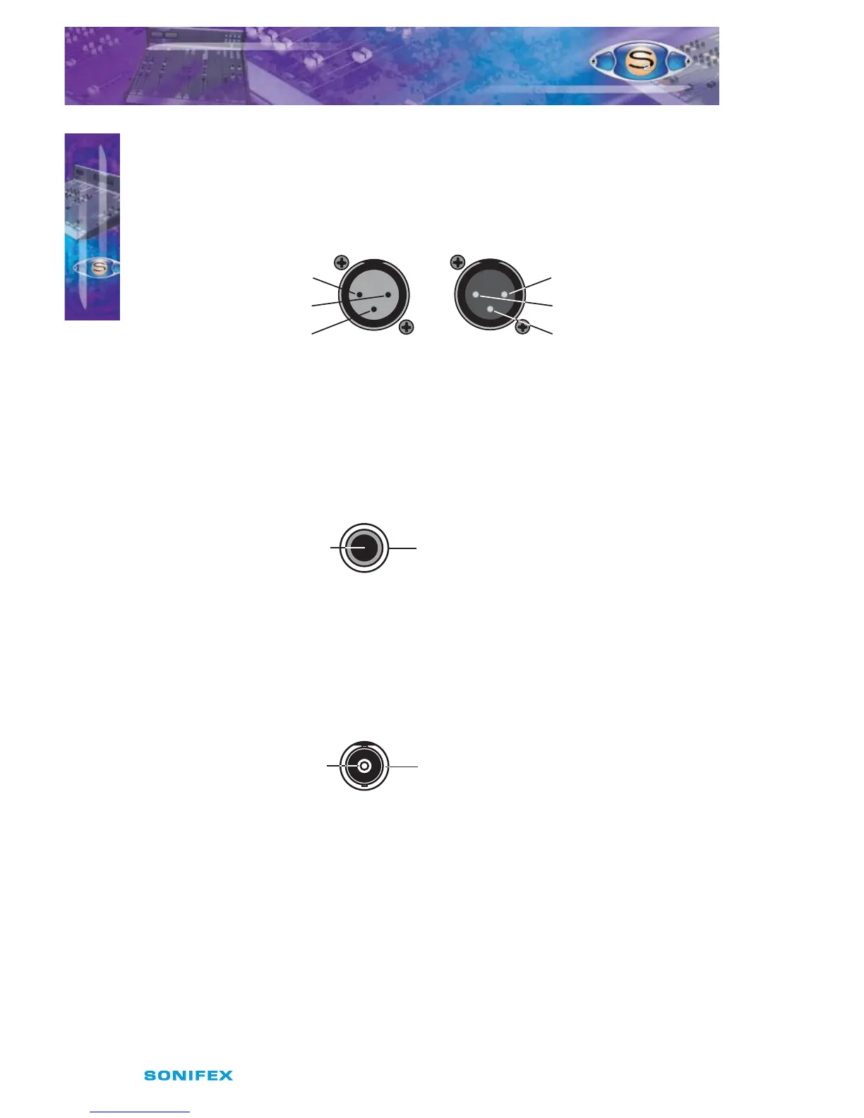
XLR 3 Pin Connectors
The following diagram shows the pin details for the 3 pin XLR sockets and plugs:
Fig 2-3 : XLR Connectors.
RCA Phono Connector
This connector is used on the Stereo Gram Channel and the S/PDIF inputs on the digital
input/output channels.
Fig 2-4 : RCA Phono Connector.
BNC Connector
This connector is used for the Word clock inputs on the PGM and AUD output channels.
Fig 2-5 : BNC Connector.
INSTALLATION NOTES
INSTALLATION NOTES
2
Pin 2. Hot (In Phase) Signal
Pin 1. Ground (Screen) Signal
Pin 3. Cold (Out Of Phase) Signal
3 Pin Socket
(Female)
Line, Mic &
AES/EBU Inputs
C/F, L/R Stereo &
AES/EBU Outputs
3 Pin Socket
(Male)
Pin 2. Hot (In Phase) Signal
Pin 1. Ground (Screen) Signal
Pin 3. Cold (Out Of Phase) Signal
Inner. Hot (In Phase) Signal Outer. Ground (Screen) Signal
Gram & S/PDIF
Inputs
RCA Phono
(Female)
Inner. Hot (In Phase) Signal Outer. Ground (Screen) Signal
Word Clock
Inputs
BNC (Female)