S2 User Handbook
29
ON Selection
The ON button works in conjunction with the fader and is used to control channel remotes,
routing, timers, etc. The button shows various states. When unlit the channel is o. Flashing
red indicates that the channel has been selected to ON but remains unrouted i.e. neither
PGM or AUD is selected. Steady red indicates that the channel is ON and “armed”, ready
for the fader to be raised. Raising the fader changes the illumination to green indicating
that the channel is live. Alternatively, with the button unlit the fader may be raised and
the channel can be operated simply by selecting ON. The illumination in this case toggles
between unlit, channel OFF and green, channel ON. Remotes, etc, are triggered when the
fader is up and the channel ON button shows green.
Scribble Pad
A scribble pad is provided at the bottom for user labelling of the channel function
e.g. “Pres. Mic”
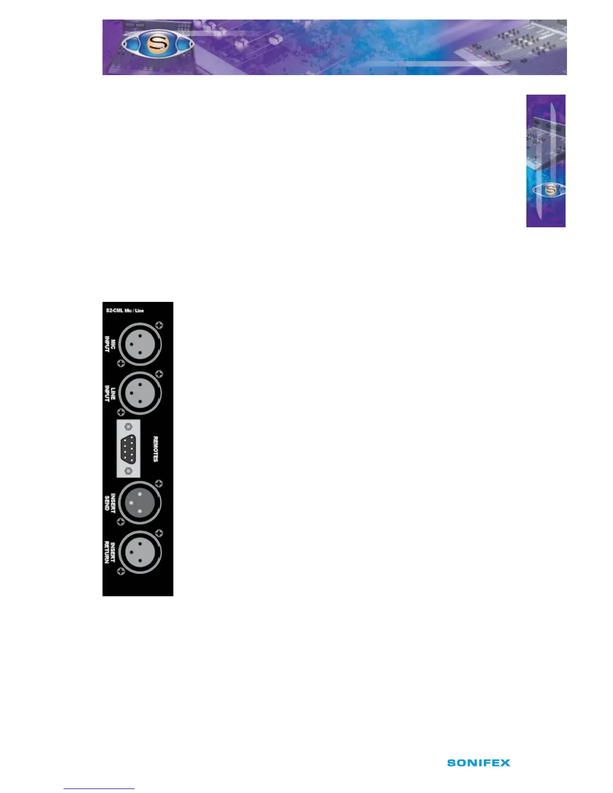
Rear Panel
Mic Input Connector
This XLR 3 pin socket is used for the microphone input and has the
following connections;
Pin 1: Screen.
Pin 2: Phase.
Pin 3: Non-phase.
Line Input Connector
This XLR 3 pin socket is used for the electronically balanced line input
and has the following connections;
Pin 1: Screen.
Pin 2: Phase.
Pin 3: Non-phase.
Remotes Connector
This 9 pin D type plug provides inputs and outputs for the following
channel functions;
t .JDDVFMJHIU
t -JOFSFNPUFTUBSU
t -JOFSFNPUFTUPQ
t $PVHISFWFSTFUBMLCBDLTXJUDI
t 5BMLCBDLNJDFOBCMF
5
S2CML MIC/LINE CHANNEL WITH EQ
S2CML MIC/LINE CHANNEL WITH EQ