S2 User Handbook
7
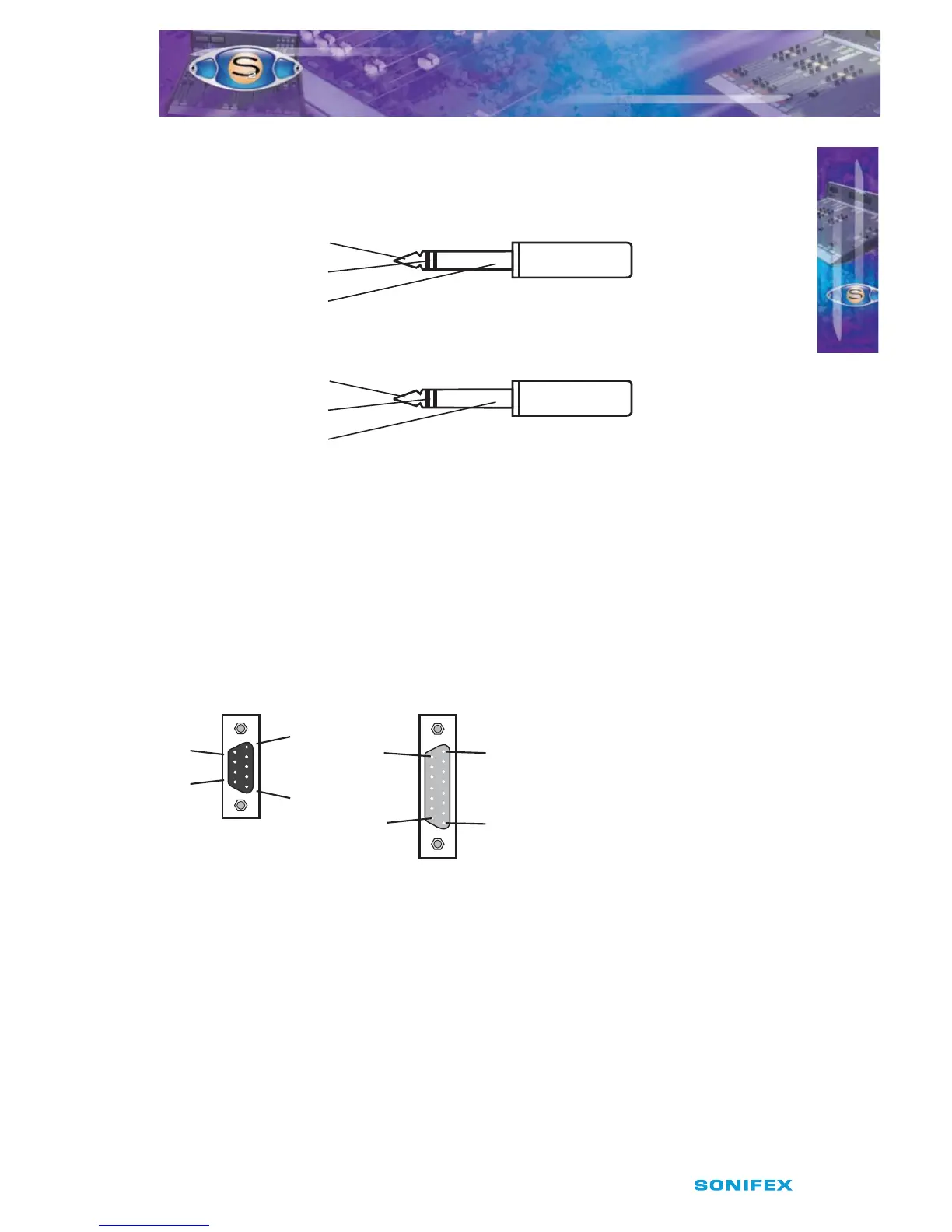
6.35mm ‘A’ Gauge Stereo Jack Plugs
‘A’ Gauge Stereo Jack Plugs can be connected as follows:
Fig 2-6 : 1/4” Jack Connectors.
D Type Connectors
Several dierent D type connectors are used on the S2. A 9 pin plug is used for the remotes
on input channels and external inputs on monitor channels. A 15 pin socket is used for the
analogue outputs and mute relays on the output channels. A 25 pin socket is used for the
audio inputs, and a 25 pin plug for the remotes, on the 6 way stereo select channel. A 9 pin
plug & socket is used for the power connections from the PSU to the mixer.
Fig 2-7 : 9 Pin & 15 Pin D-Type Connectors.
INSTALLATION NOTES
INSTALLATION NOTES
2
Tip - Left Signal
Ring - Right Signal
Sleeve - Ground (Screen) Signal
Tip - T/B Signal
Ring - Control Signal (T/B In)
Sleeve - Common
¼“ ‘A’ Gauge Stereo Jack Plug used for T/B in and T/B Out
¼“ ‘A’ Gauge Stereo Jack Plug
used for Headphones and Monitors
9 Pin D-Type Plug used
for Remotes and Ext Inputs
Pin 6
Pin 15
Pin 8
Pin 1
Pin 1
Pin 9
Pin 9
Pin 5
15 Pin D-Type Socket used for Analogue
Outpus and Mute Relays