Retour à la table des matières
2-76 1900-009-002 REV B www.stryker.com
Français
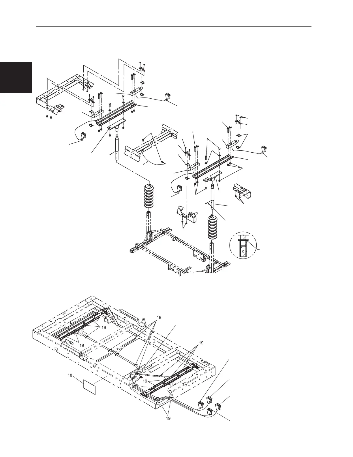
Option de support pour châssis à base fixe avec balance
Coil foot end load cell
cables and attach as shown.
Head Right
Head Left
Foot Left
Foot Right
OL190148 Rev G (Référence seulement)
X.X.
X.X.
X.X.
8
REMOVING THE AXIS TREAD AFTER
INSTALLATION BOLTS OF FIXATION
THE ROCKER.
8
T35
14
5
9
20
6
2
10
11
12
13
1 T130
4
3
16
17
10
6
3
2
1 T130
11
fi
fi
15
11
11
5
DURING THE ASSEMBLY, PLACE 2 LINES OF
TREAD Ø3/16" TI SIMPLIFY ASSEMBLY
(EX: VG50B0644).
7
7
T450
T450
T450
Enroulez les câbles de la
cellule de mesure côté pied
et attachez tel qu’illustré.
Tête droite
Tête gauche
Pied gauche
Pied droit

 Loading...