Return To Table of Contents
1-60 1900-009-002 REV B www.stryker.com
English
Service
TOOLS REQUIRED:
• #1 Phillips Screwdriver
• #2 Phillips Screwdriver
• Small Regular Screwdriver
• 1/2 in. Socket
• 3/8 in. Drive Ratchet
• 3/8 in. Combination Wrench
• 3/32 in. Allen Wrench
• 5/32 in. Allen Wrench
• Medium Strength Thread Locker (or equivalent)
• Adjustable Supports (or equivalent)
PROCEDURE:
1. Remove the mattress, raise the rails to the
highest position and apply the brakes.
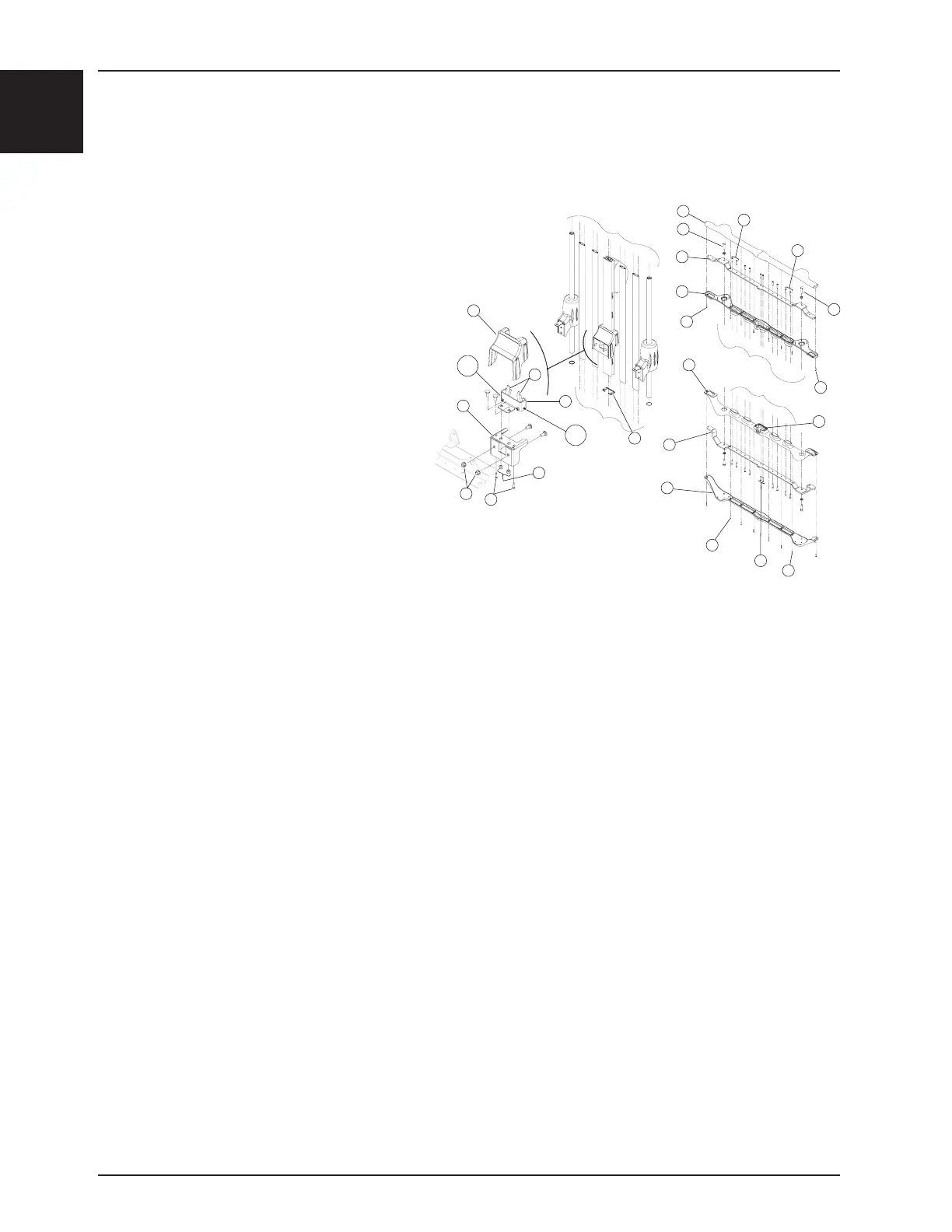
2. Using a #1 Phillips screwdriver, remove the eight
screws (A) holding the bottom half of the lower
plastic cover (B) to the top half of the lower
plastic cover (C).
3. Insert a small regular screwdriver between the
two halves of the lower plastic cover to separate
them. Use caution to avoid scratching the cov-
ers or damaging the upper cover snap pins.
4. Using a #2 Phillips screwdriver, remove the two screws (E) holding the lower end of the central column to the lower
structural member.
5. Using a 5/32 in. Allen wrench, remove the two Allen screws (A) holding the spacer (B) and the hinge (C) of both
access doors to the lower structural member (D) (see Figure 28, page 1-66). Remove the structural member and
the spacer.
Note
Apply medium strength Thread Locker to the Allen screw threads before replacing the screws.
6. Remove the access door by moving the lower end of the door to the left or right and disengaging it from the upper
hinge (H). Keep the spacer and the hinge (see Figure 28, page 1-66).
7. Using a #1 Phillips screwdriver, remove the eight screws (G) holding the top half of the upper plastic cover (H) to
the bottom half of the upper plastic cover (X).
8. Insert a small regular screwdriver between the two halves of the upper plastic cover to separate them. Use caution
to avoid scratching the covers or damaging the lower cover snap pins.
9. Lower the rail to the 14 in. locking position and place adjustable supports under the rail to support it when the
central column is removed.
10. Using a #2 Phillips screwdriver, remove the 10 screws (J) holding the upper end of the posts and the central col-
umn to the upper structural member (K).
11. Using a 1/2 in. socket, remove the two bolts and two washers (L) holding the upper end of the two guide posts to
the structural member (K).
12. Remove the lower plastic cover.
13. Lift the defective central column to remove it. Use caution to avoid damaging the seal. Set the defective coulmn
aside.
Note
The seal must be replaced if it is damaged during the procedure. Do not install a damaged seal.
SIDERAIL CENTRAL COLUMN ASSEMBLY REPLACEMENT (RAILS WITH FIXED ACCESS DOORS)
B
A
A
B
B
C
F
W
E
G
G
D
K
H
L
L
J
J
M
P
N
U,V
U,V
R
S
T
O
Q
Figure 25

 Loading...