Return To Table of Contents
www.stryker.com 1900-009-002 REV B 1-43
English
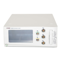
SCALE CONTROL BOARD REPLACEMENT
TOOLS REQUIRED:
• #2 Phillips Screwdriver
• Small Regular Screwdriver
• 9/16 in. Combination Wrench
• Diagonal Pliers
PROCEDURE:
Note
Unless otherwise indicated, refer to Figure 13 (see page 1-42) for this procedure.
1. Lower the foot rail completely. If it is a fixed rail, see the “Fixed Endrail Installation” procedure (see page 1-16) for
reference to temporarily lower the rail.
2. Raise the siderails to the upper position.
3. Lift the foot section and fold it towards the head end of the stretcher.
4. Using a #2 Phillips screwdriver, remove the seven screws (A) holding the foot cover plate (B) to the litter frame.
Remove the plate (see Figure 14, page 1-44).
5. Using a 9/16 in. combination wrench, remove the bolt (J), washer (H), and spacer (G) holding the fixed top socket
(B) to the accessory bracket.
6. Properly ground yourself (see “Static Discharge Precautions”, page 1-15).
7. Using diagonal pliers, cut the cable ties holding the cable to the lower plate and the accessory bracket (E).
8. Lift the cover while slowly pulling on the cables and turn it towards you until the inner side of the cover is accessible.
9. Using a small regular screwdriver, remove the load cell cable connectors (T) from the control board.
10. Disconnect the remaining cable connected to the control board. Note the positioning of the cables so they are
reconnected to the new control board properly.
11. Using a #2 Phillips screwdriver, remove the screw holding the control board grounding wire to the accessory
bracket.
12. Using a #2 Phillips screwdriver, remove the five screws (D) holding the control board (C) to the accessory bracket
cover and remove the control board.
13. Reverse the above steps to install the new control board after removing the protective film from the new control
board LCD screen.
Note
Refer to Figure 15, page 1-45, for the load cell cable connections to the control board.
14. Calibrate the scale system (see “Scale Calibration”, page 1-17).
15. Verify proper operation of the scale controls before returning the stretcher to service.
Service