EasyManuals Logo

Stryker CUB FL19F User Manual

Stryker CUB FL19F
284 pages
To Next Page IconTo Next Page
To Previous Page IconTo Previous Page
Page #78 background imageLoading...
Page #78 background image
Return To Table of Contents
1-76 1900-009-002 REV B www.stryker.com
English
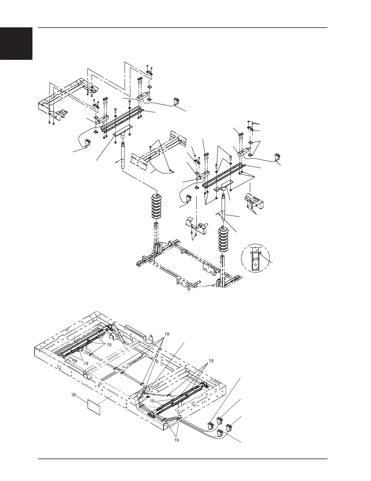
Fixed Based Frame Support with Scale Option
Coil foot end load cell
cables and attach as shown.
Head Right
Head Left
Foot Left
Foot Right
OL190148 Rev G (Reference only)
X.X.
X.X.
X.X.
8
REMOVING THE AXIS TREAD AFTER
INSTALLATION BOLTS OF FIXATION
THE ROCKER.
8
T35
14
5
9
20
6
2
10
11
12
13
1 T130
4
3
16
17
10
6
3
2
1 T130
11
15
11
11
5
DURING THE ASSEMBLY, PLACE 2 LINES OF
TREAD Ø3/16" TI SIMPLIFY ASSEMBLY
(EX: VG50B0644).
7
7
T450
T450
T450

Table of Contents

Questions and Answers:

Question and Answer IconNeed help?

Do you have a question about the Stryker CUB FL19F and is the answer not in the manual?

Stryker CUB FL19F Specifications

General IconGeneral
BrandStryker
ModelCUB FL19F
CategoryMedical Equipment
LanguageEnglish

Related product manuals