Return To Table of Contents
1-48 1900-009-002 REV B www.stryker.com
English
HEAD SECTION PNEUMATIC CYLINDER REPLACEMENT
TOOLS REQUIRED:
• (2) 1/2 in. Combination Wrenches
• 11/16 in. Combination Wrench
• #2 Phillips Screwdriver
• Medium Strength Thread Locker (or equivalent)
PROCEDURE:
Note
Unless otherwise indicated, refer to Figure 17, page 1-47, for reference for this procedure.
1. Raise the head section to the highest position, lower the rails completely and apply the brakes.
2. Using two 1/2 in. combination wrenches, remove the four locknuts (C), four shoulder spacers (H), four washers (J)
and four bolts (B) holding the head section to the two coupling bars. Remove the head section.
3. Using a #2 Phillips screwdriver, remove the nine screws holding the protective plate to the litter frame (see Figure
14, page 1-44).
4. Using two 1/2 in. combination wrenches, remove the locknut (E) and bolt (D) holding the cylinder end to the
bracket.
5. Using a 1/2 in. combination wrench, remove the two bolts and two washers (G) holding the cylinder bracket to the
litter frame.
6. Move the whole assembly slightly towards the center of the stretcher. Using an 11/16 in. combination wrench,
remove the two nuts (K) holding the threaded end of the cylinder to the bracket. Remove the pneumatic cylinder.
Note
Apply thread locker to the two bolts and the two nuts before reassembly.
7. Reverse the above steps to install the new pneumatic cylinder.
8. Verify proper operation of the head section before reinstalling the protective plate and returning the stretcher to
service.
HEAD SECTION ASSIST CABLE REPLACEMENT
TOOLS REQUIRED:
• (2) 7/16 in. Combination Wrenches
• #2 Phillips Screwdriver
PROCEDURE:
1. Raise the head section to the highest position, lower the
rails completely and apply the brakes.
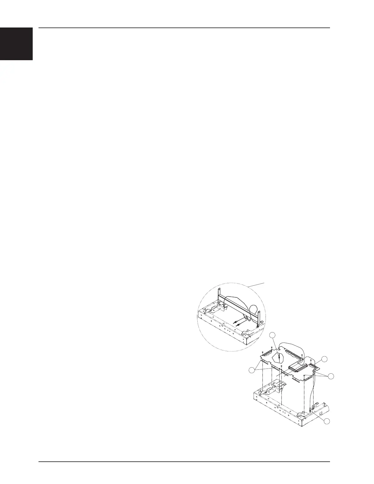
2. Using a #2 Phillips screwdriver, remove the nine screws (B)
holding the protective plate to the litter frame.
3. Using two 7/16 in. combination wrenches, loosen the two
nuts (A) at the ends of the defective cable in order to
remove it. Take note of the cable path and how the ends
are mounted at their tie points. Remove the defective cable.
4. Install the new cable.
5. Adjust the two nuts at each cable end so that the adjustment
at the activation lever end leaves no play in the activation
lever and the adjustment at the activation flap end presses
the activation flap against the cylinder release pin without activating it.
6. Verify proper operation of the head section before reinstalling the protective plate and returning the stretcher to
service.
Service
Head section assist cable path.
A
C
C
B
A
Figure 18