Return To Table of Contents
www.stryker.com 1900-009-002 REV B 1-45
English
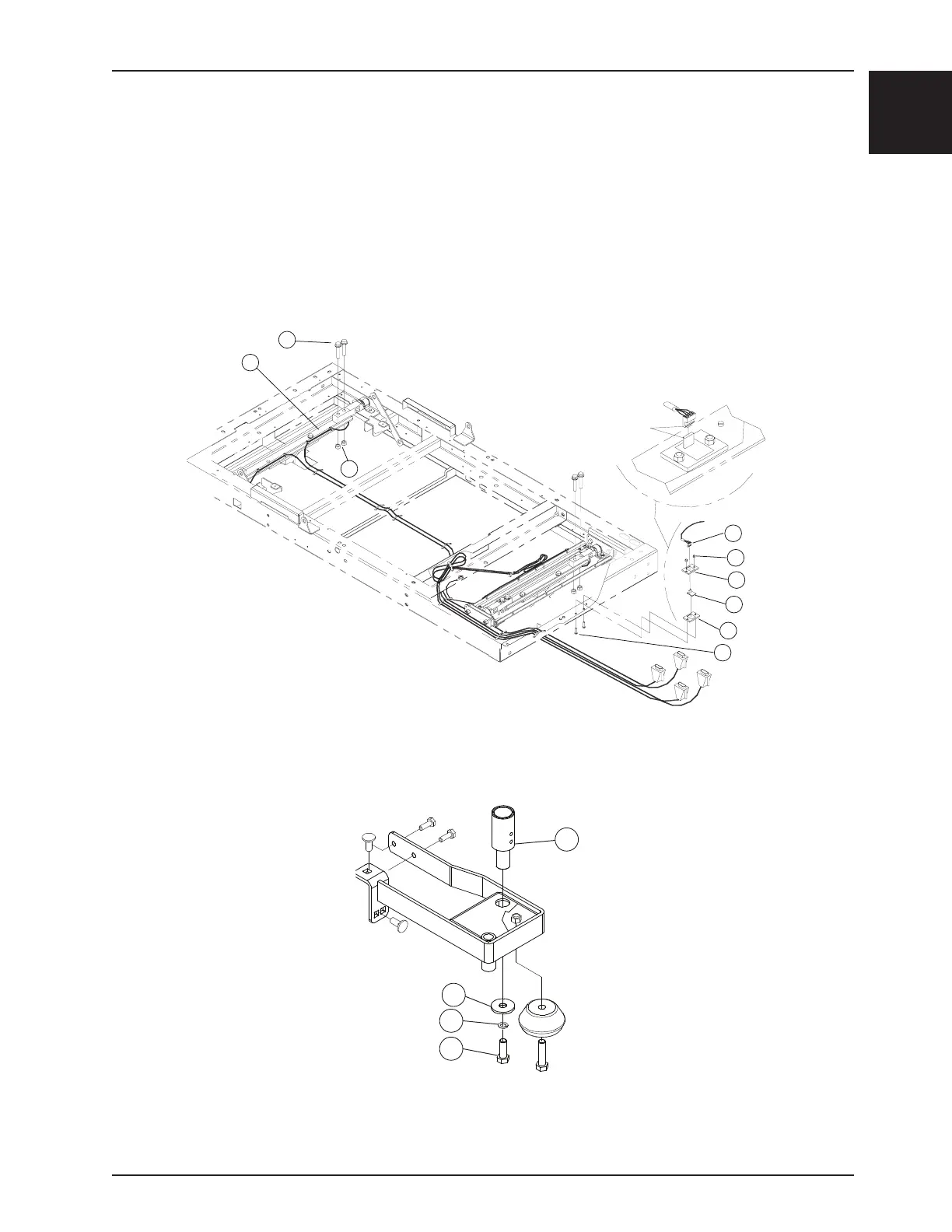
9. Using a 9/16 in. combination wrench, remove the bolt (D), washer (C), and spacer (B) holding the fixed socket (A)
to the accessory bracket. See Figure 16.
10. Using a small regular screwdriver, remove the defective load cell cable from the control board.
11. Pass the connector through the opening in the lower cover plate and remove the defective load cell.
12. Reverse the above steps to install the new load cell. When installing the new load cell, use a 0.036 in. shim to
create a gap between the load cell and the nylon support.
13. Calibrate the scale system (see “Scale System Calibration”, page 1-17).
14. Verify proper operation of all scale functions before returning the stretcher to service.
Service
A
B
C
D
POSITION #1
B
B
D
E
G
F
D
C
Figure 15
Figure 16
LOAD CELL REPLACEMENT (CONTINUED)