Return To Table of Contents
1-88 1900-009-002 REV B www.stryker.com
English
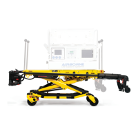
Hydraulic Base Frame Support with Scale - OL190145 Rev K (Reference only)
Item Part No. Part Name Qty.
1 VB35A1O24 Carriage Bolt 4
2 VE30A1O Nylon Hex Locknut 8
3 14662Z Lever Clamp 2
4 QP19-0270 Shaft Support Bushing 4
5 VB98A1P48 Ribbed Neck Bolt 8
6 QDF19-0977 Load Cell 4
7 VW10A12 Washer 4
8 VB18A1P36 Hex bolt 4
9 19-0952P Frame Support Plate, Head End 1
10 VE32A1P Nylon Hex Locknut 12
11 VV83A9G16 Pan Head Tapping Screw 2
12 19-0883P Frame Support Mounting Plate 2
13 M0019 Petro Canada OG2 Grease .24 kg
14 QE71-0674-F Load Cell Position Label, Head Right 1
15 QE71-0673-F Load Cell Position Label, Head Left 1
16 19-0892P Frame Support Reinforcement, Foot 2
17 VE30A1N Nylon Hex Locknut 8
18 QDF17-0138 PC Board Ground Wire 1
19 19-0156Z Slider Rail 2
20 VB15A1O24 Hex Bolt 4
21 VB35A1N24 Carriage Bolt 8
22 19-0979 Glider 2
23 QE71-0676-F Load Cell Position Label, Foot Right 1
24 19-0953P Frame Support Plate, Foot End 1
25 QE71-0675-F Load Cell Position Label, Foot Left 1
26 QDF19-0941 Angle Sensor Wire 1
27 QDF75-0470 Angle Sensor Card 1
28 19-0943 Angle Sensor Support 1
29 VE30A0G Nylon Hex Locknut 2
31 VV33A0G24 Pan Head Machine Screw 2
32 M0005 Glue .1 kg
33 QE71-0667-T Manufacturer Label 1
34 QDF9518 Black Cable Tie 17
Hydraulic Base Frame Support with Scale Option
 Loading...

