OnAir 2000M2 Digital Mixing Console
Date printed: 12.11.03 SW V 4.0 HW Modules 15-1
15 HARDWARE MODULES
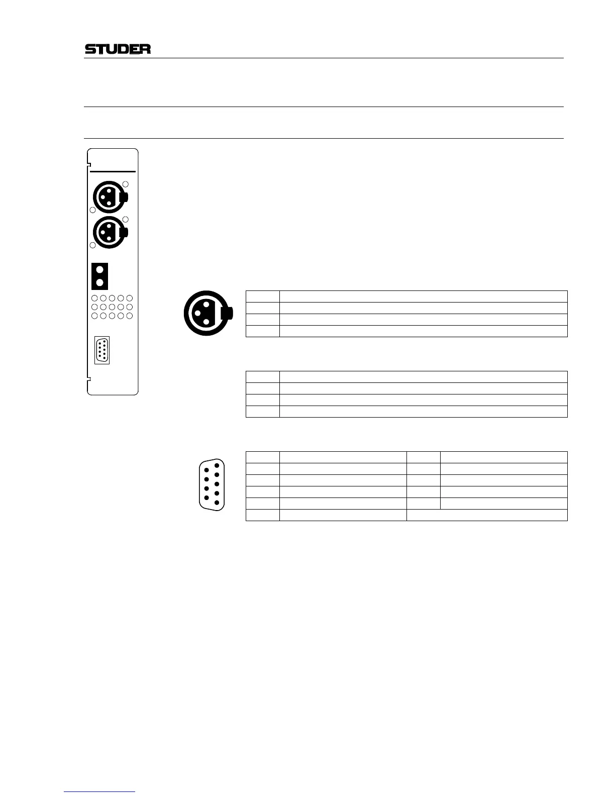
15.1 Mic Input Module 1.942.220.xx
Module with two inputs and A/B input selector. Inputs A and B are trans-
former-balanced mono microphone inputs. The maximum input level is
such that also mono line level signals can be processed if required.
The analog path has an insert point right after the preamplifier stage. Both
the insert send and insert return signals are electronically balanced. The
nominal send and return levels are +6 dBu, with 9 dB headroom for 0 dB
FS
.
The module address depends on the input channel number given to the
module and is set with a DIP switch; refer to chapter 16.1. Two modules
must not have the same address.
Pin Assignments: Microphone inputs A/B (XLR, 3pin, female):
Pin Signal
1 Chassis
2 Input +
3 Input –
INSERT connectors (Bantam jacks):
Pin Signal
T Signal +
R Signal –
S Chassis
CTRL connector (D-type, 9pin, male):
Pin Signal Pin Signal
1 CTRL OUT 1A 6 COMMON
2 +5 V SUPPLY 7 CTRL OUT 2B
3 CTRL OUT 2A 8 CTRL IN B
4 CTRL IN A 9 GND
5 CTRL OUT 1B
Two control outputs (CTRL OUT xA/B) are available for each individual
input, which can be used to start and/or cue external devices such as CD
players, R-DAT units, or a radio automation system, or for redlight sig-
naling. The control signals can be triggered by various functions and de-
pend on the selected fader start mode (INPUT CONFIG. page). For details
please refer to chapter 9. The CTRL OUT xA/B configuration is related to
the input channel and not to the fader strip.
For CTRL OUT 1A/B, four operating modes are available:
NOT ACTIVE Output is always open.
ON & FADER Output is closed (i.e. pulled to GND) when the ON key is pressed and the
fader is open.
PFL/ON & FADER Output is closed when either PFL is active (independent of the fader posi-
tion), or when the ON key is pressed and the fader is open.
ON LAMP Output is closed while the ON lamp is illuminated.
3
1
2
MIC
A
B
INSERT
SEND
RETURN
CTRL
3
1
2
3
1
2
1
2
3
4
5
6
7
8
9