OnAir 2000M2 Digital Mixing Console
15-8 HW Modules SW V 4.0 Date printed: 12.11.03
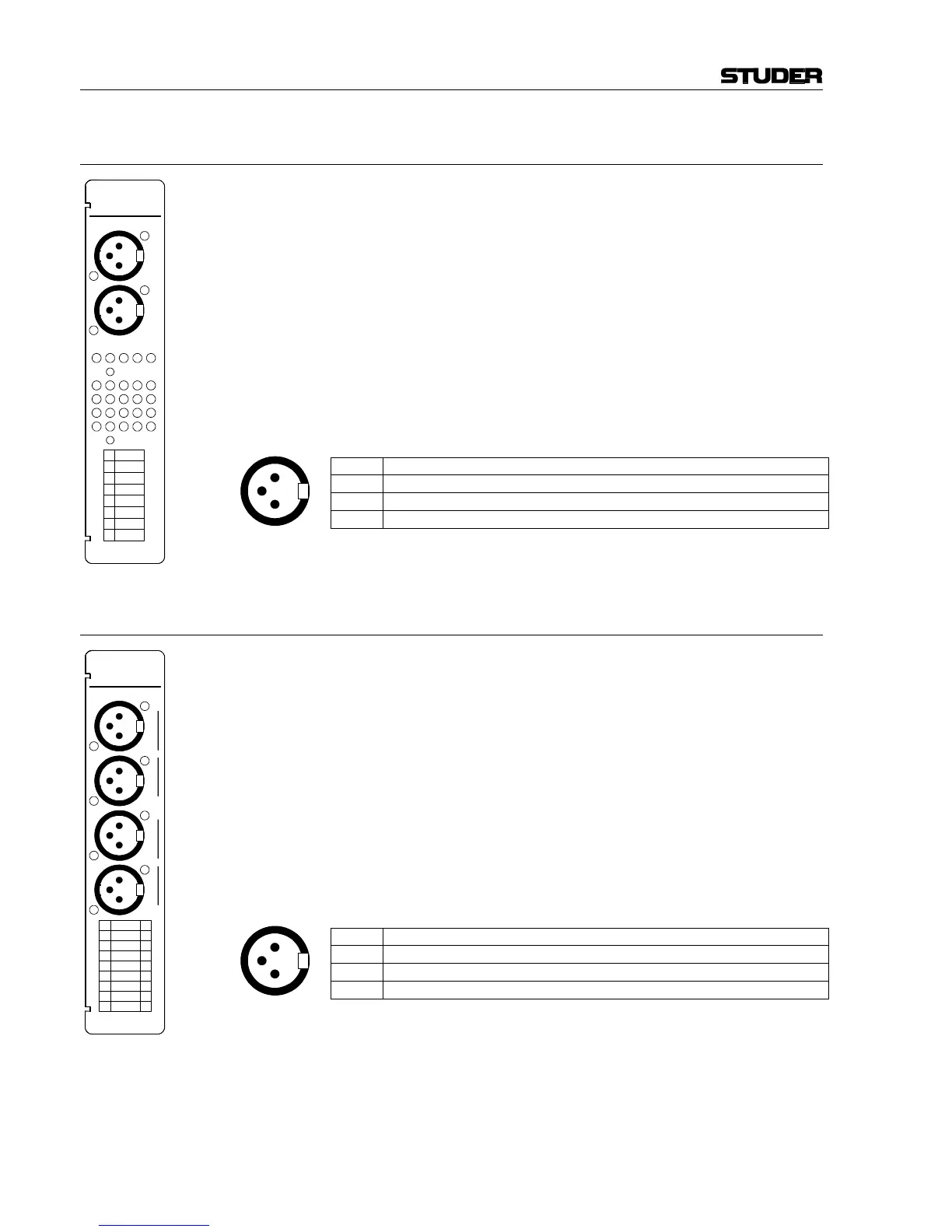
15.8 Analog Output Module 1.942.120.xx (with balancing transformers)
The analog output module provides a transformer-balanced, stereo or
mono output signal (jumper-selectable).
The output signal selection is performed on the PCB by means of labeled
jumpers.
Note: In mono mode, the output signals of the stereo DAC are added in the ana-
log domain to increase the converters' dynamic range. Therefore, if the
DAC input signal is a stereo signal, the resulting mono output level is in-
creased by 3 dB referred to the stereo output, and if the DAC input signal
is a mono signal, the resulting mono output level is increased by 6 dB.
These level differences have to be compensated by adjusting the output
level with the two trimmer potentiometers “R ADJ.” and “L ADJ.” acces-
sible from the rear of the module.
Pin Assignment: Line output (XLR, 3pin, male):
Pin Signal
1 Chassis
2 Output +
3 Output –
15.9 Dual Analog Output Module 1.942.121.xx (with balancing transformers)
The dual analog output module provides a transformer-balanced, dual ste-
reo or mono output signal (jumper-selectable).
The output signal selection is performed on the PCB by means of jumpers;
refer to chapter 16.5.
Note: In mono mode, the output signals of the stereo DAC are added in the ana-
log domain to increase the converters' dynamic range. Therefore, if the
DAC input signal is a stereo signal, the resulting mono output level is in-
creased by 3 dB referred to the stereo output, and if the DAC input signal
is a mono signal, the resulting mono output level is increased by 6 dB.
These level differences have to be compensated by adjusting the output
level with trimmer potentiometers located on the PCB; refer to chapter
16.5 for component locations.
Pin Assignment: Line outputs A/B (XLR, 3pin, male):
Pin Signal
1 Chassis
2 Output +
3 Output –
3
1
2
3
1
2
1
3
2
LINE OUT
L
R
R ADJ.
L ADJ.
PGM
REC
AUD
AUX 1
AUX 2
(N–1) A
(N–1) B
1
3
2
1
3
2