OnAir 2000M2 Digital Mixing Console
5-4 Master Functions SW V 4.0 Date printed: 12.11.03
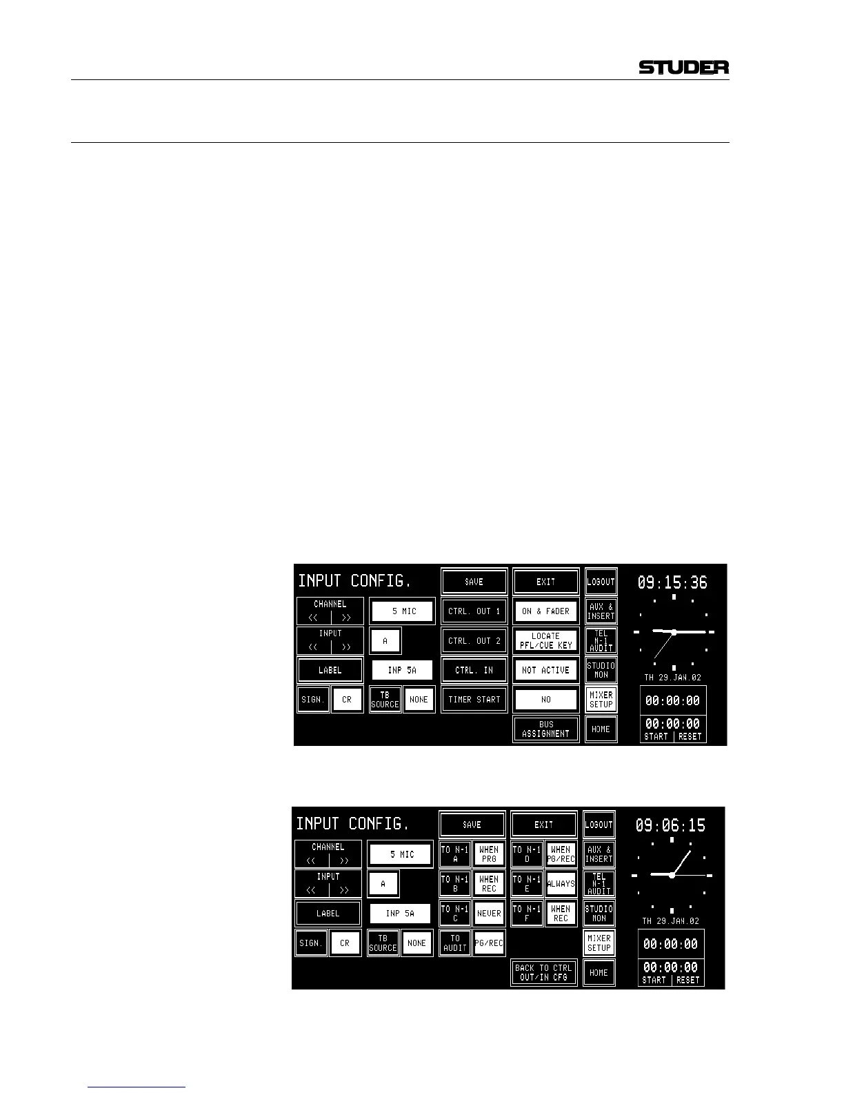
5.3.1 Additional N–1 Outputs
Starting with SW V3.0, four additional N–1 outputs (N–1C...F) are avail-
able, provided that no Insert 3/4 module is installed in the console. Their
respective levels are also part of a snapshot. When upgrading from a SW
version earlier than V3.0, a hardware modification is required on the DSP
Board – please ask your Studer distributor for additional information.
Conditions: • A Dual Analog Output Module or a Digital Output Module must be
installed in order to output the four additional N–1C...F signals;
• On the Dual Analog Output Module, output mode must be set to “Ste-
reo” (jumper setting), refer to chapter 16.5.
• For the Digital Output Module, this selection is not required.
• For bus assignment on the Dual Analog Output Module (jumper set-
ting), also refer to chapter 16.5; plug the jumper for output A to position
OUT1, the jumper for output B to position OUT2.
Then, the four N–1 signals are output on the following connectors:
N–1C on output A, left channel; N–1D on output A, right channel
N–1E on output B, left channel; N–1F on output B, right channel.
• For bus assignment on the Digital Output Module (DIP switch setting),
refer to chapter 16.6; set DIP switch A to N–1C/D, and DIP switch B to
N–1E/F according to the table in chapter 16.6.
Then, the four N–1 signals are output on the following connectors:
N–1C/D on output A, left/right channel
N–1E/F on output B, left/right channel.
When touching BUS ASSIGNMENT on this page, it changes as follows,
allowing to select the six N–1 and the audition bus assignments: