OnAir 2000M2 Digital Mixing Console
12-14 Configuration SW V 4.0 Date printed: 12.11.03
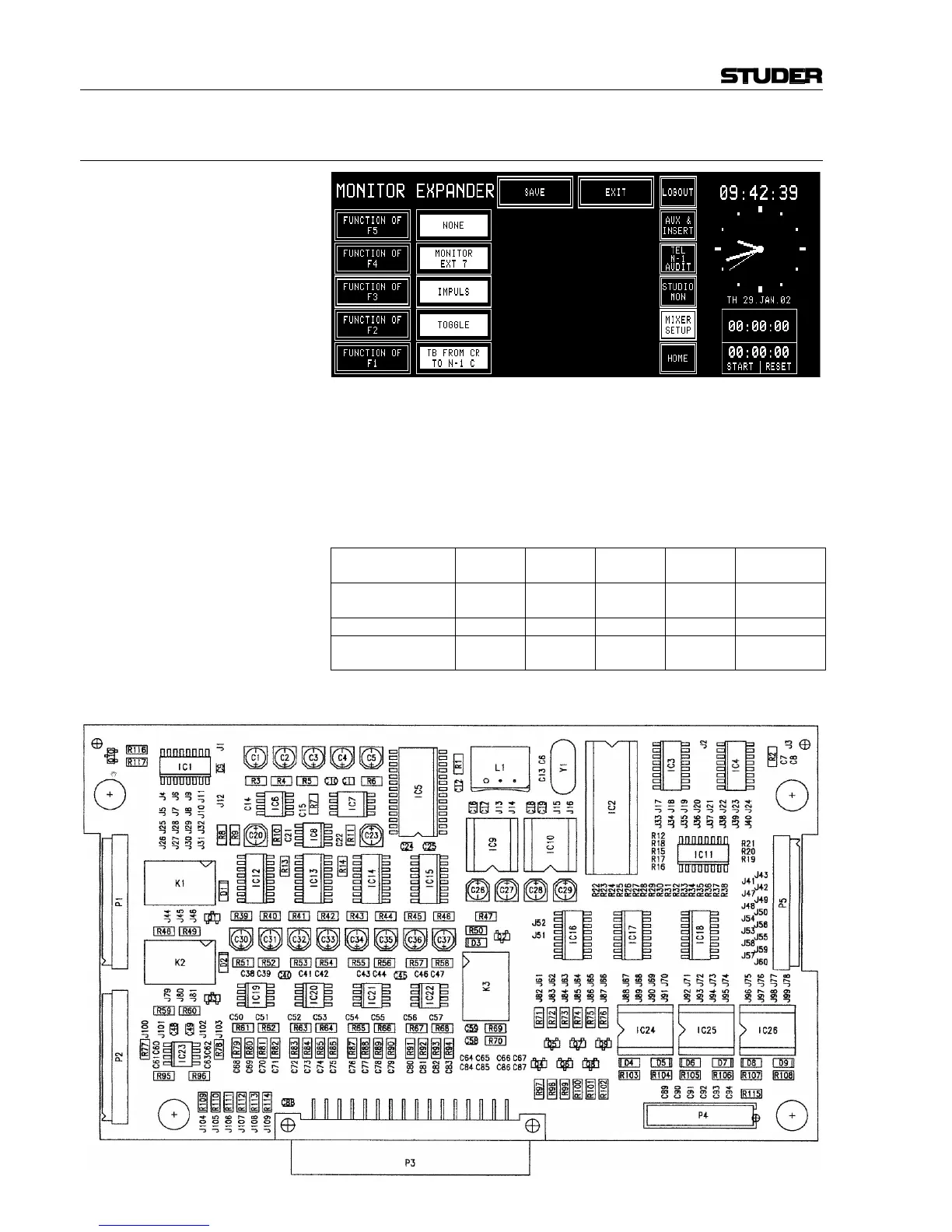
12.2.11 Monitor Extension (Optional)
The MONITOR EXPANDER page allows to configure the functionality of
the F1 to F5 keys. The different possible functions are described on the
next pages and refer to the screenshot above. For additional information
on the monitor extension see the block diagram in chapter 15.14.
Modification: Please note that for the functions IMPULS, TOGGLE, and TB FROM CR
TO... described later, a modification is required on the Monitor Expander
Board 1 (1.942.136.xx); this allows to send the F1...5 (Fx) output signals
to the EXTENSION CTRL1 connector of the Monitoring Module.
Signal Name
F1 / CTRL
OUT1
F2 / CTRL
OUT 2
F3 / CTRL
OUT 3
F4 / CTRL
OUT 4
F5 / CTRL
OUT 5
Cut
J62-J83,
J32-J31
J63-J84,
J11-J10
J64-J85 J65-J86 J66-J87
Connect
J32-J83 J11-J84 J51-J85 J52-J86 IC2 pin16-J87
Output Pin on
EXTENSION CTRL1
3 4 5 6 7
In addition, switch no. 8 of the DIP switch on the Monitor Expander Board
2 (1.942.137.xx) must be set to OFF.