OnAir 2000M2 Digital Mixing Console
4-6 Channel Functions SW V 4.0 Date printed: 12.11.03
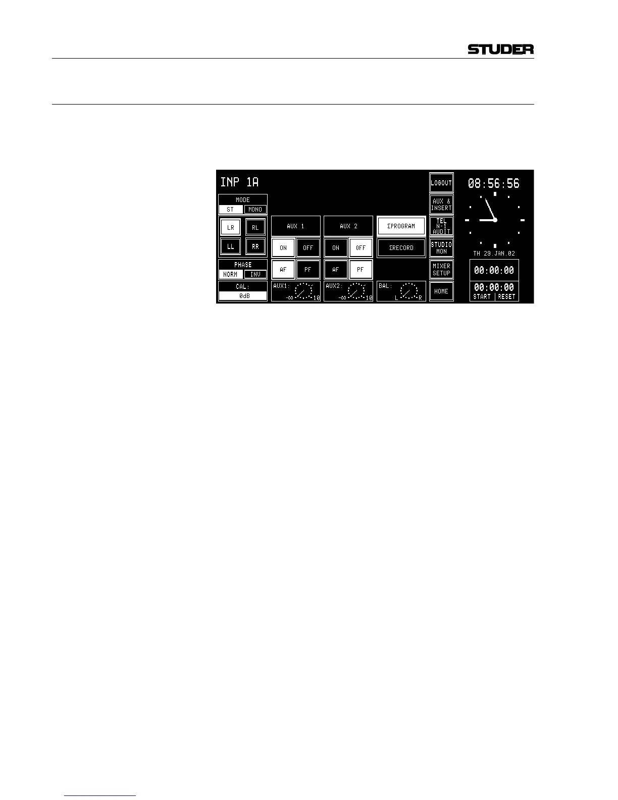
4.4.4 Channel Control Page, Line Input
The Channel Control page for a line input is opened if either the AUX, the
PAN, or the Input touch-screen field on the channel screen is touched,
provided that the selected input module is an analog line input or a digital
input.
MODE Line level inputs have a MODE field which defines whether the input is
processed in “ST”(-ereo) or in “MONO” mode. In mono mode the stereo
input signal from the input module is added to a mono signal and attenu-
ated by 3 dB.
Stereo signals are processed in the following modes:
LR: Normal stereo mode;
RL: Left/right channel swapped;
LL: Left signal on both channels;
RR: Right signal on both channels.
PHASE The phase (of the left input path only) is inverted by touching the “INV”
part of the PHASE touch-screen field; “INV” is highlighted. Touching
“NORM” de-activates the phase inversion. Only in the “RR” case, the
phase inversion takes place in the R input path.
CAL In the CAL field, the gain deviation referred to nominal level setting is dis-
played; max. deviation: ±15 dB, adjustment with the first rotary encoder.
AUX 1 / AUX 2 The AUX 1/2 “ON” and “OFF” touch-screen fields route the channel sig-
nal to the corresponding auxiliary bus, if “ON” is selected (and high-
lighted).
The “AF” / “PF” touch-screen fields allow selection whether the signal is
tapped after- (AF) or pre-fader (PF). The current selections are high-
lighted.
The AUX levels (–∞...+10 dB; 0 dB position is marked with a dash) are
adjusted with the second and third rotary encoder. The settings are shown
in the fields right above the rotary encoders as well as on the correspond-
ing symbols on the channel screen.
The bus assignment is performed with the “ΣPROGRAM” and “ΣREC-
ORD” touch-screen fields.
BAL The fourth rotary encoder adjusts the position of the stereo image, the
BAL indicator shows the adjusted position.