External PSU for OnAir 2000
E6 External PSU Date printed: 12.11.03
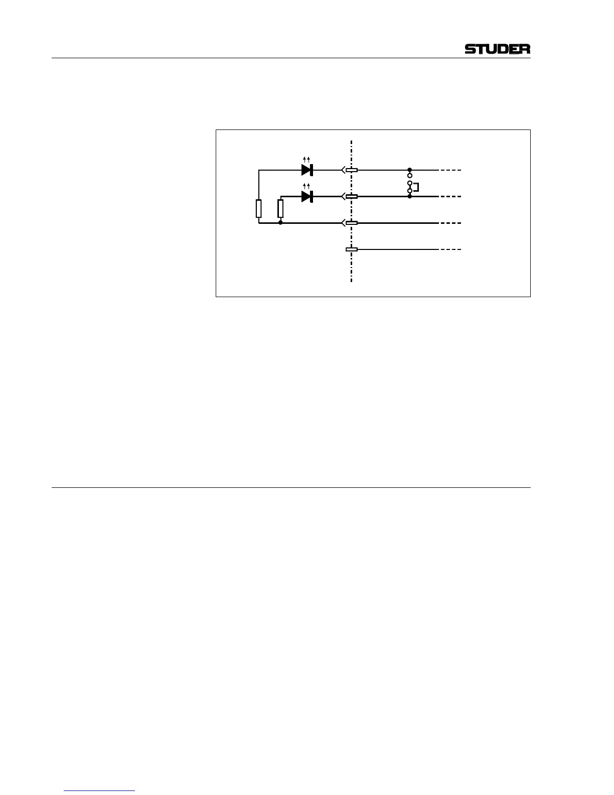
either one or two LEDs – preferably flashing types, with integrated current
limiting resistors for 5 V
DC
operation. For connection, please refer to the
diagram below.
Alarm Jumper in the Console On the Redundancy PSU Connection PCB 1.942.107, a jumper is located.
If P11 and P12 are connected with jumper JS1 (refer to the diagram
above): The ALARM_1 and ALARM_2 signals are linked, so that one
single power alarm LED can be used.
If P12 and P13 are connected with jumper JS1 (as shown in the diagram
above): The ALARM_1 and ALARM_2 signals are separate, so that two
individual power alarm LEDs can be used.
Single Supply Unit Operation An OnAir 2000 Mixing console equipped with the supply redundancy
option can be operated with one external supply unit only.
Please note that no supply redundancy is available in this application.
3 SETUP
Please follow the steps below for correct setup!
1. Set the POWER switches of both external power supply units to the OFF
position.
2. Connect the DC supply cables between the console and the external power
supply units.
3. Connect the mains inlets of the external power supply units to the mains
using appropriate cables. Please note that for fully redundant operation,
the two mains cables should be connected to two different phases.
4. Switch the external power supply units ON.
P8/1
ALARM_1
P8/2
ALARM_2
P8/3
+5 V
P8/4
DGND
*
Redundancy PSU Connection PCB
1.942.107
* Resistor value(s)
depending on
LED operating
current
AL1
AL2
*
P11
P12
P13
JS1