OnAir 2000M2 Digital Mixing Console
Date printed: 12.11.03 SW V 4.0 DIP Switches and Jumpers 16-1
16 DIP SWITCHES AND JUMPERS
Note: The DIP switch and jumper positions are printed on the PCBs, except for
the TB Mic Input Module and the Analog Output Module; for these two
assemblies, drawings have been included in the following chapters for
component location.
16.1 Input Modules (Mic, Line, Digital)
Input Module Address: The physical input module's input channel number is defined with DIP
switches or jumpers. The assignment of the input module relative to the
fader strip, however, is done dynamically in the CHANNEL ROUTING
page.
On the Mic, Line, and Digital Input Modules, the input channel number is
set with DIP switches, according to the following table:
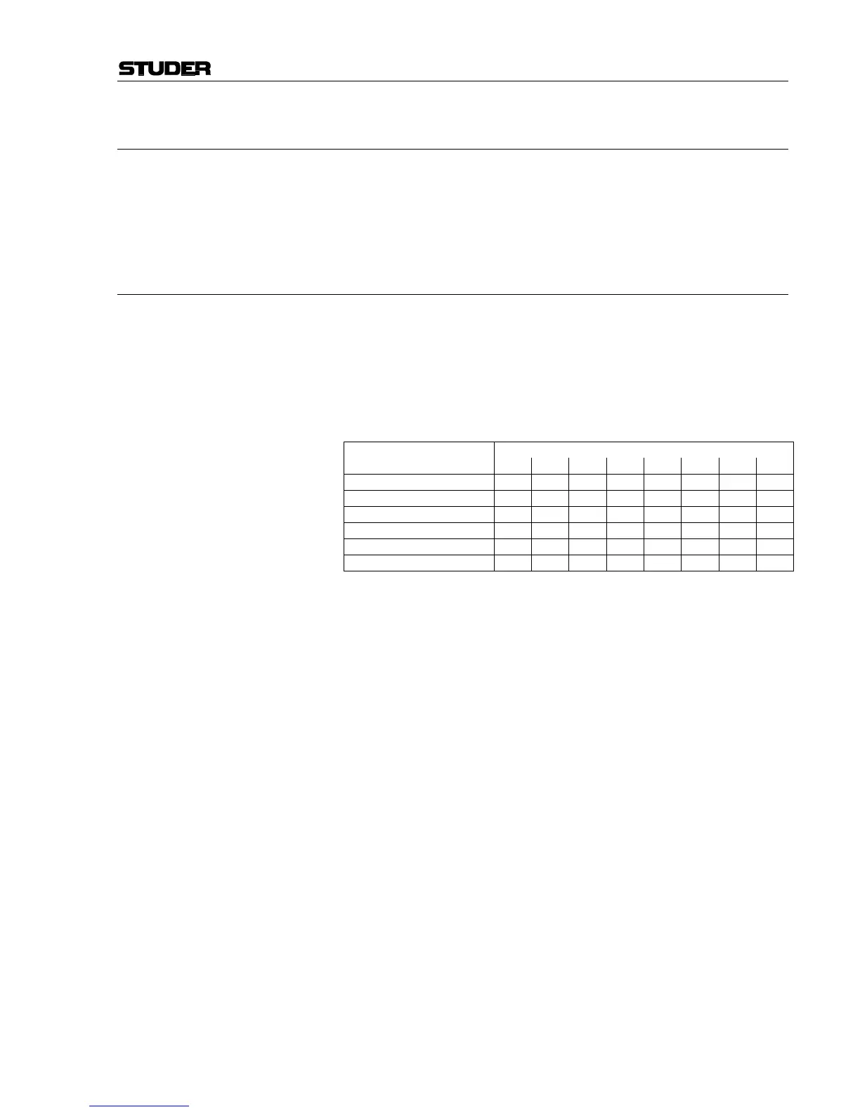
DIP Switch No.:
Input Channel No.: 1 2 3 4 5 6 7 8
1, 7, 13, 19
OFF ON ON ON ON ON ON OFF
2, 8, 14, 20
ON OFF ON ON ON ON ON OFF
3, 9, 15, 21
OFF OFF ON ON ON ON ON OFF
4, 10, 16, 22
ON ON OFF ON ON ON ON OFF
5, 11, 17, 23
OFF ON OFF ON ON ON ON OFF
6, 12, 18, 24
ON OFF OFF ON ON ON ON OFF
On the Talkback Mic Input Module, however, the address is set with a
jumper (see chapter 16.2).