External PSU for OnAir 2000
Date printed: 23.08.04 External PSU E5
2 WIRING AND HARDWARE INFORMATION
The optional external power supply unit for the OnAir 2000 console is
installed in a 19” 2U cabinet. If it is used, the standard internal power sup-
ply of the console is replaced by a connection unit with two 30-pin
Siemens connectors. Each of these allows connection to one external sup-
ply unit.
Usually, full redundancy is desired (order no. 1.942.109.00). In such a
case, two identical supply units are used. Their mains inlets should
preferably be connected to different phases of the mains. Each unit has its
own power switch and contains one (earlier versions: two) primary
switching power supply/ies and one secondary DC/DC converter. Each of
the external power supply units is connected with its own DC cable to the
console.
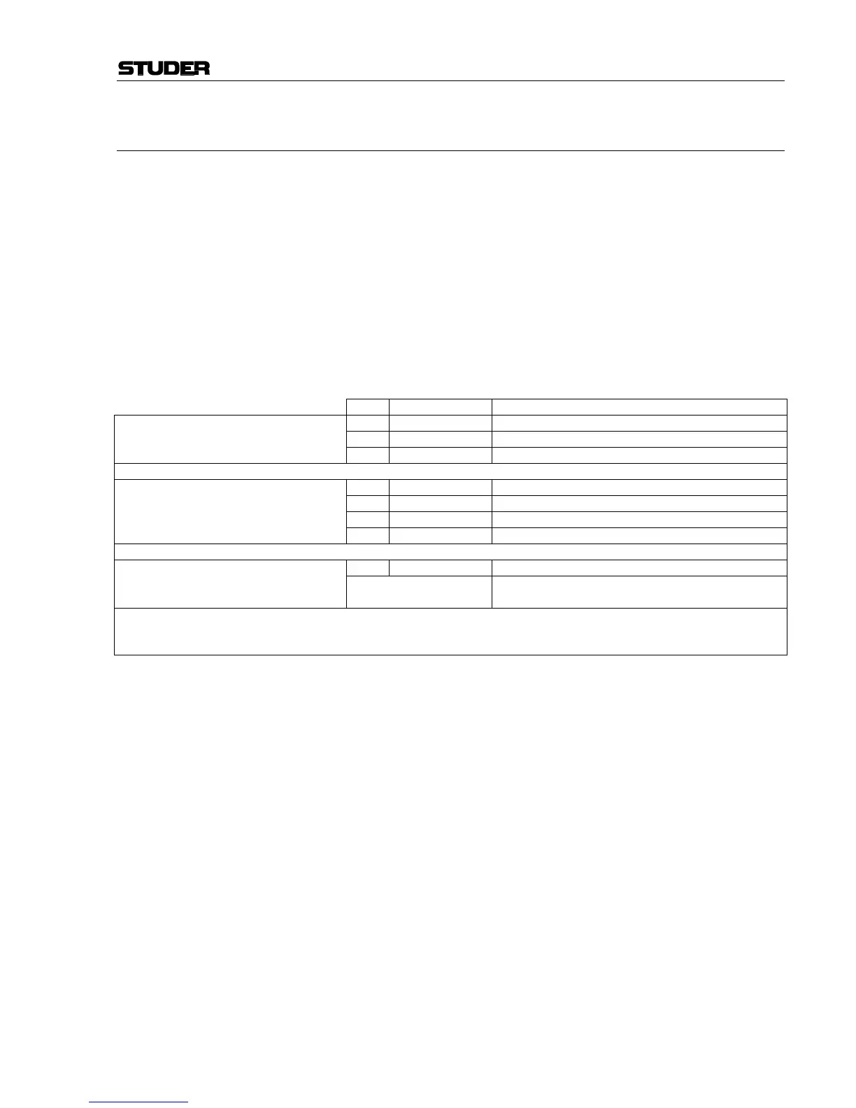
Pcs Order no. Designation
2 * 1.918.220/222*** Power Supply
2 1.918.225 Cable 2 m (longer cables on request)
Redundancy PSU Set (1.942.109),
consisting of:
1 ** 1.942.106 Connection Unit
2 89.20.2011 Power Supply Main (earlier versions)
or 1 89.20.2017 Power Supply Main (current versions)
1 1.942.105 *** Power Supply
* Power Supply (1.918.220 or 1.918.222***),
consisting of:
1 1.918.221 Sub Board PSU
1 1.942.107 Redundancy PSU Connection Board** Connection Unit (1.942.106),
consisting of:
Cables to DSP and Level Meter Interface
+ miscellaneous mounting hardware
*** Earlier versions only: The Power Supply PCB 1.942.105.83 for OnAir 2000M2 Modulo devices requires an additional capacitor in paral-
lel with C11 and C16, due to the increased current drawn by the additional Remote Master and Slave PCBs. This capacitor is referenced
with “C*” in the diagram 1.942.105.83; it is mechanically mounted within the case (1.918.222) and hard-wired to the PCB.
Front Panel LEDs The external power supply unit has a red and four green LEDs on its front
panel; the four green LEDs indicate presence of the four supply voltages
(+15 V, –15 V, +5 V, and +24 V); the red “POWER ALARM” LED is on
if one of the DC supply voltages should fail. Should this happen, a power
alarm is triggered in addition.
Alarm Output The power alarm output signal is sent to pin7A of the DC supply
connector. The power alarm output is a relay contact (40 V/200 mA max.).
Its behaviour depends on the setting of the jumper JS1 on the "Sub Board
for PSU" PCB.
Pin7A of the DC supply connector is normally floating, and pulled to GND
when power alarm is active (JP1 and JP2 connected with JS1, default
factory setting).
In the alternate jumper position (JP2 and JP3 connected with JS1), pin7A
is normally pulled to GND and becomes floating when alarm is active.
Note: It is recommended to leave the jumper setting as it is. Should it be
changed, the POWER ALARM LED on the front panel of the supply unit
will be illuminated if everything is alright, and vice versa.
Alarm Indicator(s) in the Console If required, power alarm indicator LEDs can be installed in a prominent
position within the console. For this purpose, connector P8 on the
Redundancy PSU Connection PCB has been provided. It allows to connect