OnAir 2000M2 Digital Mixing Console
Date printed: 12.11.03 SW V 4.0 Machine Control 9-1
9 MACHINE CONTROL
The OnAir 2000M2 provides different control inputs and outputs. These
can be used e.g. for switching a channel on and off, or for starting, stop-
ping, and cueing of the connected source unit (as CD/cartridge/MD play-
ers, tape recorders, or a CAB system). The control inputs and outputs are
input-related and are re-assigned together with the input signal to the re-
spective fader strip if the channel routing is changed.
Each audio input holds two control outputs and one control input on D-
type connectors. The signals are:
• CTRL OUT 1 (normally used for fader start, but configurable for other
functions; see chapter 9.2.1)
• CTRL OUT 2 (configurable functions see chapter 9.2.2)
• CTRL IN (configurable functions see chapter 9.3.1)
The status of the output signals depends on the control elements of the
fader strip (keys 1 to 3, fader, input selection, channel routing, and output
bus assignment), as well as on the console configuration.
Each channel consists of either two (A/B input module) or six (hex input
module) audio inputs. Each audio input has its own control input and two
control outputs allowing to control every external source separately.
9.1 Keys and LEDs
Key 1/LED 1 The first key (labeled “PFL”) is always used to activate/deactivate the PFL
function; if active, LED 1 is illuminated.
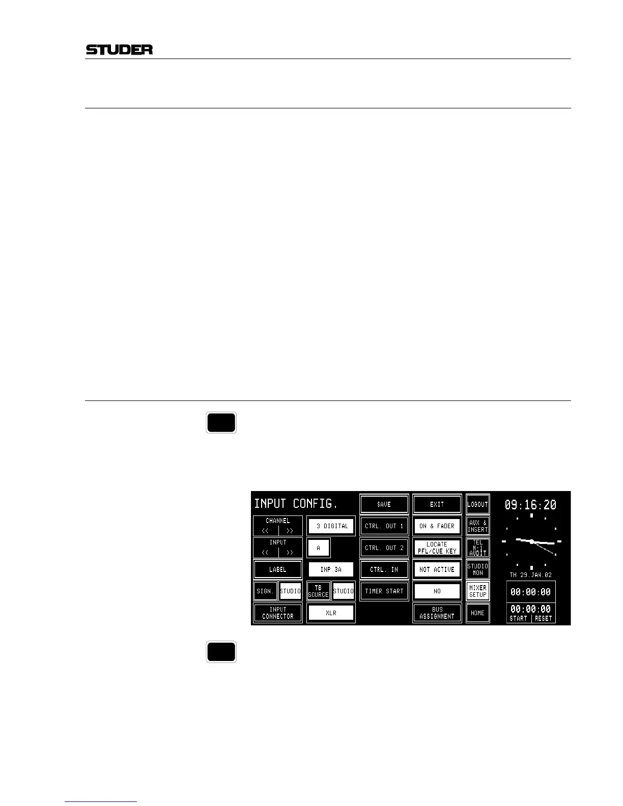
The PFL function can affect the CTRL OUT1 and/or CTRL OUT2 control
signals, depending on the configuration. This configuration is performed in
the center part of the INPUT CONFIG. page and is identical for all types
of input modules.
Key 2/LED 2 The second key (labeled “ON”) is used either to switch the channel ON or
to toggle the channel ON/OFF, depending on the configuration of key 3.
This function affects the CTRL OUT1 control signal. LED 2 always indi-
cates the channel's ON/OFF status.
PFL
ON