OnAir 2000M2 Digital Mixing Console
Date printed: 12.11.03 SW V 4.0 DIP Switches and Jumpers 16-5
16.3 Telephone Hybrid Interface
The DIP Switch on the Telephone Hybrid Control Module must always be
set as follows:
DIP switch no.:
1 2 3 4 5 6 7 8
OFF OFF ON ON ON ON ON OFF
16.4 Analog Output Module
The Analog Output Module has labeled jumpers located on the PCB for
mono/stereo selection and output signal selection.
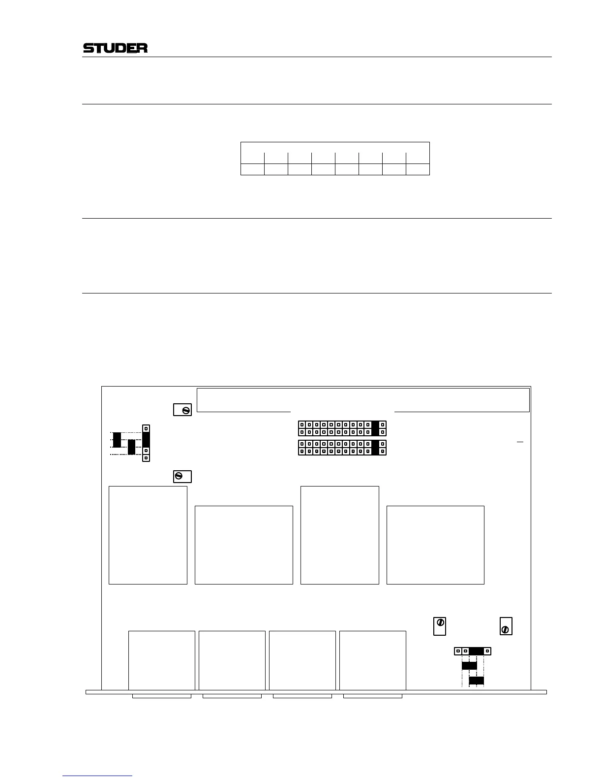
16.5 Dual Analog Output Module
Dual Analog Output Modules have jumpers for mono/stereo selection and
output signal selection, individually for each output A and B.
Notes: Jumper and trimmer potentiometer locations are different for the two PCB
versions ...81 and ...82, as indicated in the two drawings below.
Jumper positions OUT1 and OUT2 can be used for assignment of four
additional N–1 outputs C...F; refer to chapter 5.3.1.
RA1
OUTPUT LEVEL
A LEFT
RA2
OUTPUT LEVEL
A RIGHT
A STEREO
A MONO
RA3
OUTPUT LEVEL
B LEFT
P60
P61
P62
P63
RA4
OUTPUT LEVEL
B RIGHT
P59
B STEREO
B MONO
P30
P17
P57
P44
P19
P6
P46
P33
PFL
TALKBACK
N–1 B
N–1 A
OUT1
AUX2
AUX1
AUDITION
RECORD
PGM
OUT2
A
B
P31
P32
P45
P58
P18
Dual Analog
Output Module
1.942.121. 81