OnAir 2000M2 Digital Mixing Console
15-6 HW Modules SW V 4.0 Date printed: 12.11.03
15.6 TB Mic Input Module 1.942.219.xx (Option)
The TB Mic Input Module is used for connecting an internal or external
talkback microphone (jumper-selectable). It offers a supply voltage for the
internal unbalanced goose-neck electret microphone (order no.
1.942.218.xx), and a transformer-balanced XLR input for an external mic
with jumper-selectable 48 V phantom power. The balanced input is avail-
able on a 3-pin AMP connector on the PCB as well. The input gain is set
with a jumper (LO/HI) and is adjustable with a rear-panel trimmer potenti-
ometer. An on-board limiter protects the output from an accidental over-
load.
The analog TB output is transformer-balanced and fed to an XLR (at the
rear panel) and an AMP connector (on the PCB); an unbalanced AMP out-
put is available on the PCB. The level of the balanced output is adjusted
with a rear-panel trimmer potentiometer. The analog TB output must be
activated by an external control signal or by a wire bridge in a dummy plug
on the CTRL connector (connect pins 2-6 and 4-9)
For information on installation of an optional TB Mic Input Module and
on configuration of the console as well as for jumper settings and pin as-
signment of the on-board connectors please refer to chapter 16.2.
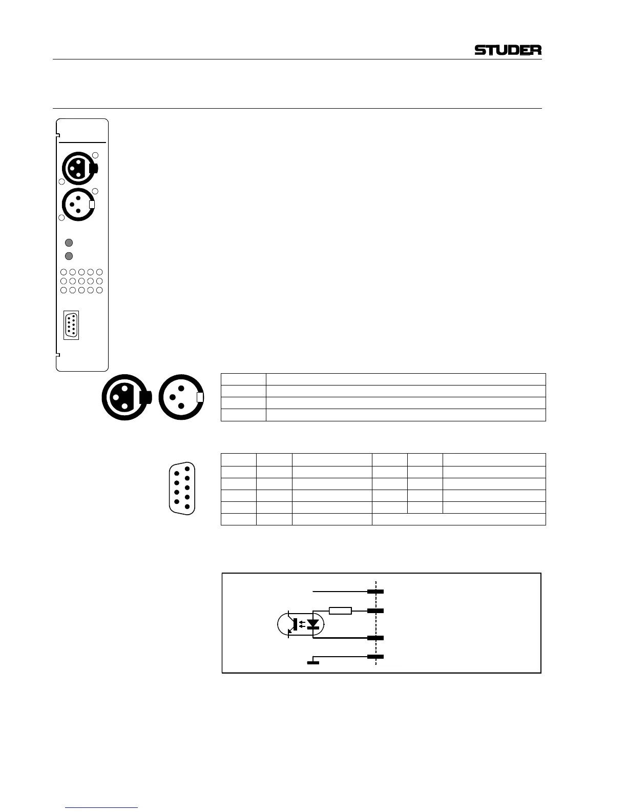
Pin Assignments: TB MIC IN/OUT (XLR, 3pin, female/male)
Pin Signal
1 Chassis
2 Input +/Output +
3 Input –/Output –
CTRL connector P4 (D-type, 9pin, male), P8 (on PCB AMP, 4pin, male)
P4, pin P8, pin Signal P4, pin P8, pin Signal
1 - n.c. 6 2 TB CTRL IN +
2 1 +5 V OUT 7 - n.c.
3 - n.c. 8 - n.c.
4 3 TB CTRL IN – 9 4 GND
5 - n.c.
Control Input: If a control signal is applied to “TB CTRL IN+” and “TB CTRL IN–”, the
EXT TB MIC OUTPUT is activated.
Notes: “TB CTRL IN +” can be wired either to “+5 V OUT” or to an external
supply (max. +15 V
DC
). An active low control signal is connected between
“TB CTRL IN – ” and “GND”. The input is an opto-coupler input with an
internal 1 kΩ current limiting resistor.
The “+5 V OUT” output can supply up to 50 mA.
3
1
2
1
2
3
4
5
6
7
8
9
3
1
2
1
3
2
3
1
2
TB MIC
IN
OUT
MIC GAIN
OUTPUT LEVEL
CTRL
P4 pin2/P8 pin1 +5V OUT
P4 pin9/P8 pin4 GND
1 kΩ
P4 pin6/P8 pin2 TB CTRL IN+
P4 pin4/P8 pin3 TB CTRL IN–
+5 V