OnAir 2000M2 Digital Mixing Console
Date printed: 12.11.03 SW V 4.0 HW Modules 15-3
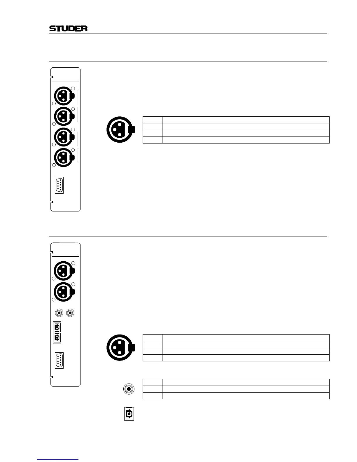
15.2 Analog Line Input Module 1.942.230.xx (w. transf.); 1.942.232.xx (el. bal.)
The analog line input module has an input selector for two stereo input
sources (A and B). Inputs A and B are equivalent.
The module address depends on the input channel number given to the
module and is set with a DIP switch; refer to chapter 16.1. Two modules
must not have the same address.
Pin Assignments: Line inputs A/B (XLR, 3pin, female):
Pin Signal
1 Chassis
2 Input +
3 Input –
CTRL connector (D-type, 9pin, male): Please refer to chapter 15.1 for
details.
15.3 Digital Input Module 1.942.240.xx
The digital input module has an input selector for two digital signals A and
B. Each of the inputs has all connectors (XLR, Cinch, TOSLINK) required
for supporting the AES/EBU and S/PDIF standards.
The most important C-bits (Professional, Audio, Emphasis, Sampling rate,
Stereo) are read on the interface and transferred to the host controller.
Audio and Emphasis bits are processed. The digital source needs not being
synchronized to the console since the digital input module is equipped
with a 20 bit sampling frequency converter (SFC).
The module address depends on the input channel number given to the
module and is set with a DIP switch; refer to chapter 16.1. Two modules
must not have the same address.
Pin Assignments: AES/EBU inputs A/B (3pin, female):
Pin Signal
1 Chassis
2 Input +
3 Input –
S/PDIF connectors A/B (RCA/Cinch):
Pin Signal
Inner Input
Outer GND
Optical connectors A/B (TOSLINK): For optical-fibre cables.
CTRL connector (D-type, 9pin, male): Please refer to chapter 15.1