OnAir 2000M2 Digital Mixing Console
15-10 HW Modules SW V 4.0 Date printed: 12.11.03
15.11 Analog Insert Module 1.942.160.xx (Option)
The analog insert module has two electronically balanced, stereo insert
sends and insert returns that can be assigned to any of the input channels,
or to the program or the record bus.
Selection of the channel to be assigned to the insert is performed on the
AUX MASTER/INSERTS page by means of the fourth rotary encoder.
Selection is possible only if the corresponding insert is set to OFF (i.e., the
return signal is not routed to the output).
The insert assignment is related to an input and not to a fader. If the input
signal is re-routed, the insert is re-assigned accordingly.
The insert send is always active; the return, however, is only active if the
ON field of the corresponding insert (on the AUX MASTER/INSERT
page) is activated.
The sends are equipped with an internal limiter located before the D/A
converter to avoid overloads. Nominal insert level is +6 dBu with 9 dB
headroom (i.e. maximum level is +15 dBu for 0 dB
FS
).
Up to two insert modules (analog, digital, or mixed) can be installed in a
console. The insert 1/2 (1st module) or insert 3/4 (2nd module) selection is
performed with a DIP switch for each module; refer to chapter 16.7.
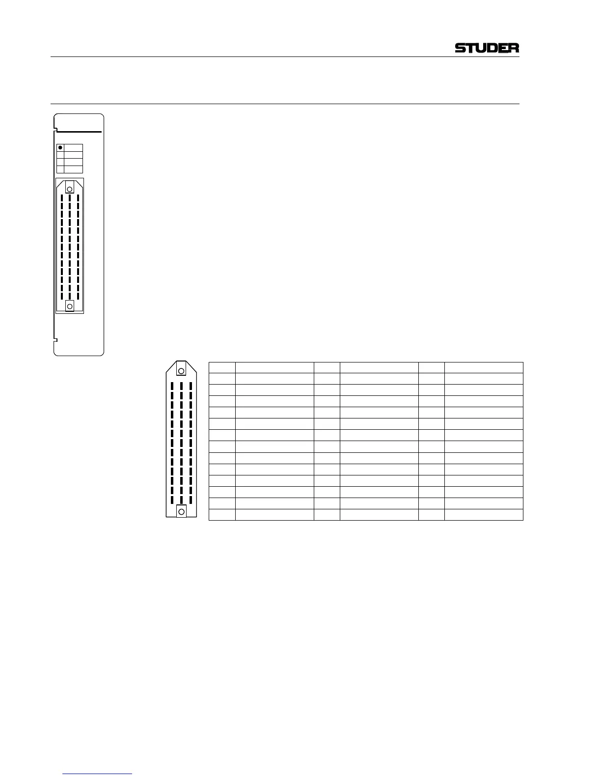
Pin Assignment: INSERT (Siemens, 39pin, male):
Pin Signal Pin Signal Pin Signal
1A Send 1/3 + left 1B Send 1/3 – left 1C Chassis
2A Return 1/3 + left 2B Return 1/3 – left 2C Chassis
3A Send 1/3 + right 3B Send 1/3 – right 3C Chassis
4A Return 1/3 + right 4B Return 1/3 – right 4C Chassis
5A Send 2/4 + left 5B Send 2/4 – left 5C Chassis
6A Return 2/4 + left 6B Return 2/4 – left 6C Chassis
7A Send 2/4 + right 7B Send 2/4 – right 7C Chassis
8A Return 2/4 + right 8B Return 2/4 – right 8C Chassis
9A n.c. 9B n.c. 9C Chassis
10A n.c. 10B n.c. 10C Chassis
11A n.c. 11B n.c. 11C Chassis
12A n.c. 12B n.c. 12C Chassis
13A n.c. 13B n.c. 13C n.c.
C
1
A
2
3
4
5
6
7
8
9
10
11
12
13
B
INSERT
ANALOG
DIGITAL
INS 1/2
INS 3/4