OnAir 2000M2 Digital Mixing Console
16-2 DIP Switches and Jumpers SW V 4.0 Date printed: 12.11.03
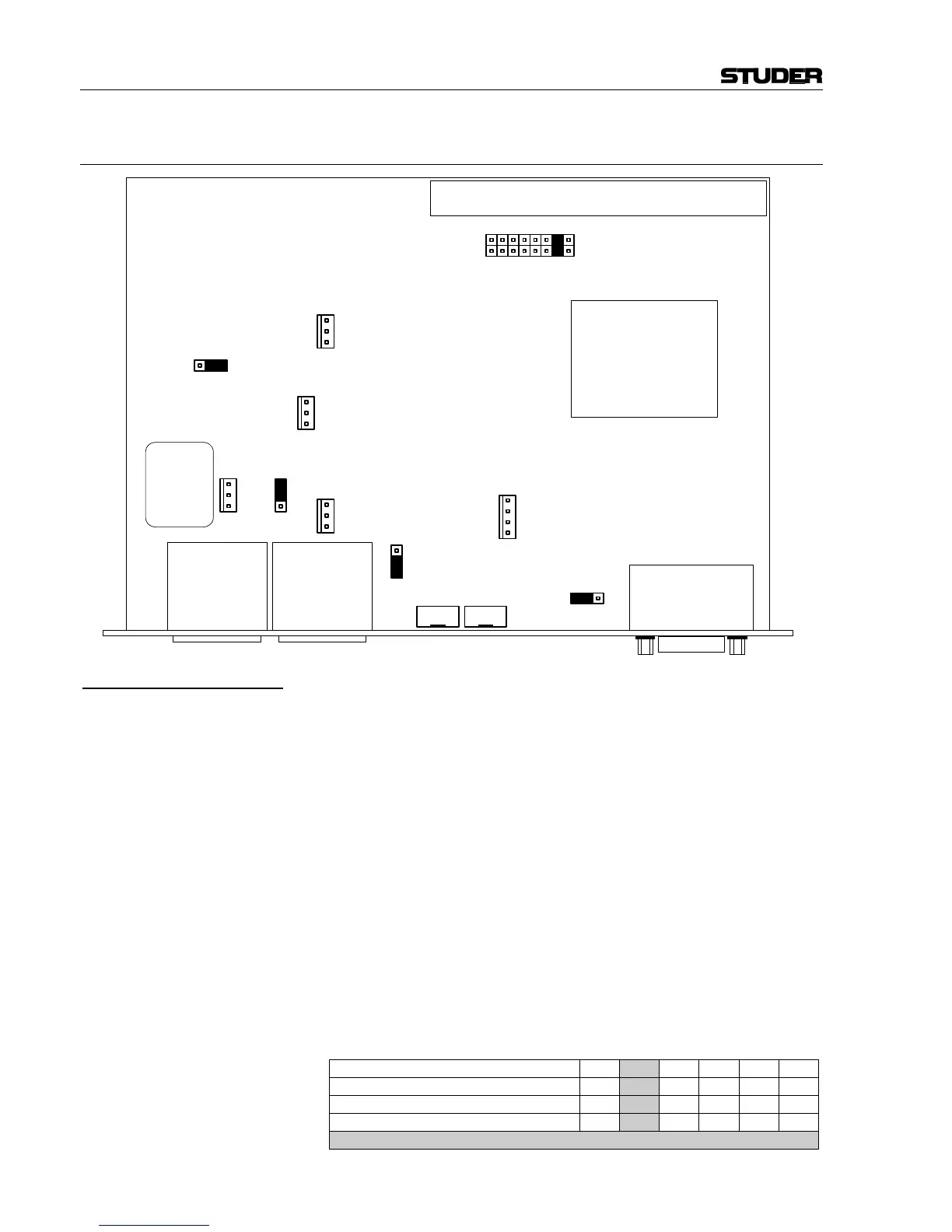
16.2 TB Mic Input Module
Jumper for Module Position: When installing the TB Mic Input Module in an OnAir 2000M2 console,
the console configuration must be updated.
6-Channel Console • Configure as 12-channel console (on DSP Board: only CFG1 inserted).
• Connect the module to IMB2 of the DSP Board; any desired board ad-
dress can be selected; factory jumper setting is IN2 (see Note 1).
• Select MIXER SETUP / SYSTEM CONFIG. / INPUT, select
CHANNEL 8, and set TB SOURCE to CR.
12-Channel Console • Configure as 18-channel console (on DSP Board: only CFG0 inserted).
• Connect the module to IMB3 of the DSP Board; any desired board ad-
dress can be selected; factory jumper setting is IN2 (see Note 1).
• Select MIXER SETUP / SYSTEM CONFIG. / INPUT, select
CHANNEL 14, and set TB SOURCE to CR.
18-Channel Console • Configure as 24-channel console (on DSP Board: neither CFG0 nor
CFG1 inserted).
• Connect the module to IMB4 of the DSP Board; any desired board ad-
dress can be selected; factory jumper setting is IN2 (see Note 1).
• Select MIXER SETUP / SYSTEM CONFIG. / INPUT, select
CHANNEL 20, and set TB SOURCE to CR.
Note 1: The INx jumper position is related to one of the 6-channel sections of the
console, as shown in the table:
Jumper position on TB Mic Input Module IN1 IN2 IN3 IN4 IN5 IN6
On 6-ch console, select channel no.
7 8 9 10 11 12
On 12-ch console, select channel no.
13 14 15 16 17 18
On 18-ch console, select channel no.
19 20 21 22 23 24
factory setting
IN8
IN7
IN6
IN5
IN4
IN3
IN2
IN1
AGND
IN B
IN A
P7
EXT MIC
ON
OFF
PHANTOM PWR
AGND
OUT B
OUT A
P9
TB OUT BAL
AGND
AGND
IN
P6
INT ELEC-
TRET MIC
LO
HI
GAIN
OFF ON
EXT TB CTRL
EXT INT
MIC
AGND
AGND
OUT
P5
TB OUT
UNBAL
GND
INSIG_N
INSIG_P
P8
EXT TB
CTRL
EXT_VCC
RA1
MIC GAIN
RA2
OUTPUT
LEVEL
P4
P1
P3P2