OnAir 2000M2 Digital Mixing Console
Date printed: 12.11.03 SW V 4.0 DIP Switches and Jumpers 16-3
24-Channel Console • One of the input modules being already installed must be sacrificed
when installing a TB Mic Input Module.
• Make sure that the correct address is set on the TB Mic Input Module;
e.g., if the removed input module was no. 12 (or 18, or 24), setting the
jumper to position “IN6” is correct (see table above).
• Connect the TB Mic Input Module to the same daisy-chain connector as
the removed input module was connected to.
• Select MIXER SETUP / SYSTEM CONFIG. / INPUT, select CHAN-
NEL “x”, and set TB SOURCE to CR (“x” is the number of the input
module that was removed).
Remaining Jumpers:
MIC INT/EXT Input selection – either internal unbalanced microphone (i.e. the standard
electret TB mic with fixed supply voltage), connected to P6, or external
balanced microphone with switchable phantom power, connected to P2 or
P7.
PHANTOM PWR ON/OFF Selection of 48 V phantom power for the balanced mic input (P2 or P7).
GAIN HI/LO For the internal standard electret TB mic, the LO position (nominal input
level: –60 dBu) is used. In HI position, the mic input gain is increased by
20 dB, i.e. nominal input level –80 dBu.
EXT. TB CTRL ON/OFF Activates or deactivates the external TB control input on P4 or P8.
IN1...8 Address selection – refer to the “Jumper for Module Position” paragraph
above; factory setting: IN1.
Connections:
TB Mic Input Module Connect the flat cable to the IMB connector on the DSP Board which cor-
responds to the selected console configuration. In a 24-channel console the
TB Mic Input Module is connected to the same daisy-chain connector as
the removed input module was connected to.
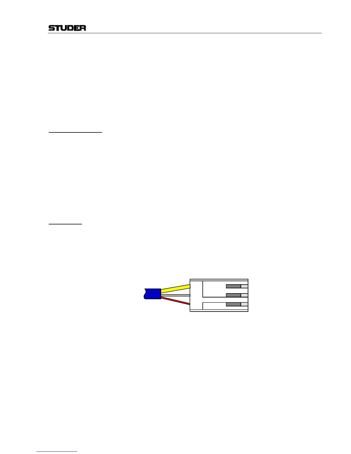
TB Mic Insert the contacts of the microphone cable into the AMP connector hous-
ing contained in the set, and make sure that the contact retaining springs
engage:
Then plug the AMP connector to P6 of the TB Mic Input Unit.
3 - screen (yellow)
2 - white
1 - red