Clocking
Using an external clock crystal is a bit more involved than using an internal oscillator source.
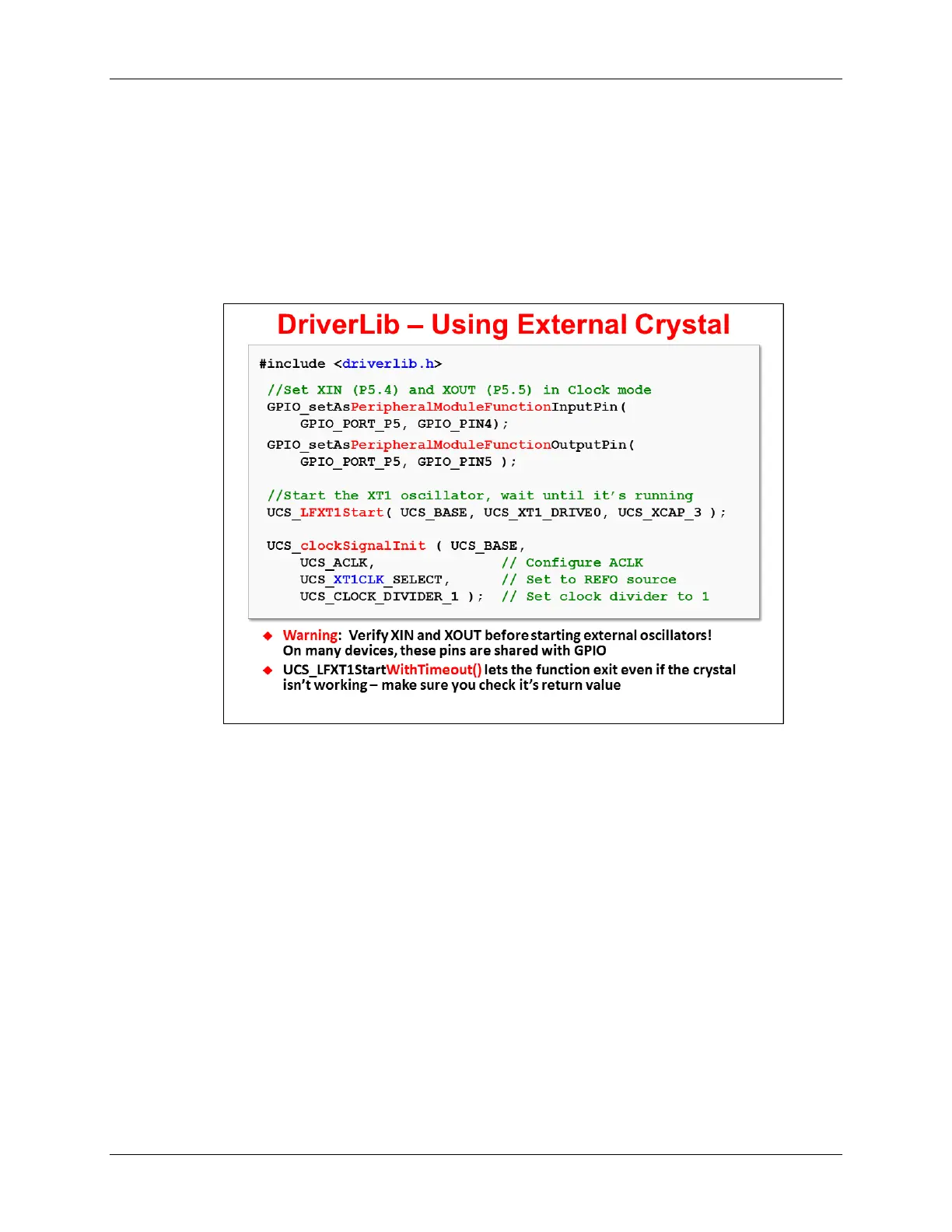
Before you can configure the clock using the same UCS_clockSignal_init() function, you must:
− Setup the XIN/XOUT as clock pins. (On many devices, these pins default to their GPIO
modes.)
− The crystal oscillators must be started up before they can be used to source a clock. The
clock API provides two start functions: one will not exit until the oscillator has started,
while the other one can timeout and return even if the crystal hasn't started running
correctly. (If you use the latter, make sure you evaluate its return value.)
As pointed out in the slide, there are two functions that can be used to start each of the crystal
oscillator sources: one will continue until the crystal has started (and will run forever); while the
other provides a timeout option.
The crystal startup functions provide two arguments for selecting the crystal drive strength and
on-chip load capacitance.
− For Low Frequency (LF) crystals, the drive strength option allows you to tune minimize
the power needed to drive the crystal; also, you can select on-chip capacitor that meets
your crystals requirements. (Additional external capacitors can be added if necessary.)
− For HF crystals, different crystal or resonator ranges are supported by choosing the
proper drive settings. In this case, you will need to use external capacitors.
If you choose to use the XT1 (and/or XT2) inputs with an external clock signal on XIN (XT2IN),
you need to set them for bypass mode. Conveniently, DriverLib provides UCS functions for
putting the interfaces into bypass mode.
The optional lab exercise for this chapter provides a crystal oscillator example for you to explore.
MSP430 Workshop - MSP430 Clocks & Initialization 4 - 17