Timer Details: Configuring TIMER_A
OUTMOD = 2 (“Toggle/Reset” mode)
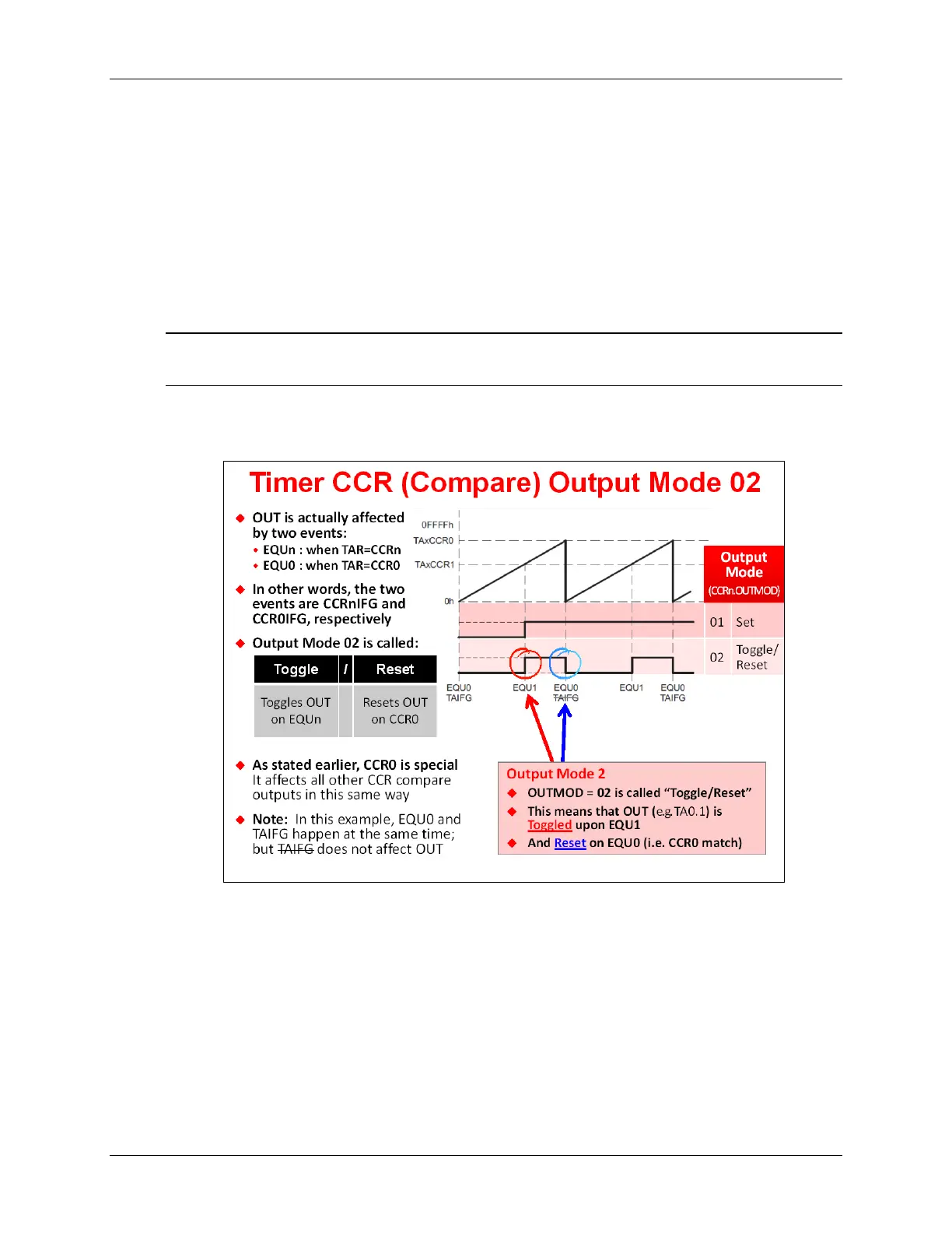
OutputMode 2 is a bit more interesting than the previous output modes. Notice how this mode is
called “Toggle/Reset”. Each of these names corresponds to a different event.
• Toggle - This means that OUT
n
should be toggled whenever TAR=CCR
n
• Reset - This implies that OUT=0 (i.e. reset) whenever TAR=CCR0
In other words, when the OutputModes are defined by two names, the first one dictates the value
of OUTn whenever the TAR=CCR
n
(i.e. whenever EQU
n
becomes true). The second name
describes what happens to OUT
n
whenever TAR=CCR0.
Note: Remember what we said earlier, CCR0 is often used in a special way. This is another
example of how CCR0 behaves differently than the rest of the CCR’s.
Looking at the diagram below, we can see that in OutputMode 2, the OUT1 signal appears to be
a pulse whose duty cycle (i.e. width) is proportional to the difference between CCR0 and CCR1.
By showing both OUTMOD=1 and OUTMOD=2 in the same diagram, you can see how the value
of OUT
n
can be very different depending upon the OutputMode selected.
6 - 26 MSP430 Workshop - Timers