EasyManuals Logo

Texas Instruments MSP430 Student Guide

Texas Instruments MSP430
398 pages
To Next Page IconTo Next Page
To Previous Page IconTo Previous Page
Page #303 background imageLoading...
Page #303 background image
(Extra Credit) Lab 6c Timer using Up Mode
13. Add the jumper wire to your board to connect the timer output to the LED.
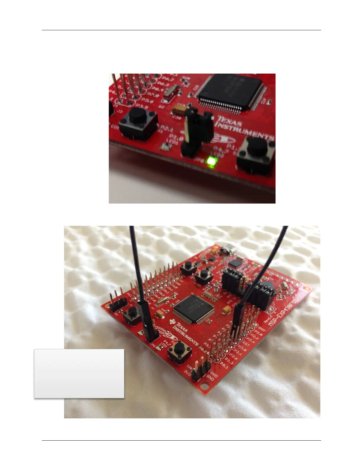
a) Remove the jumper (JP8) that connects the Red LED to P1.0.
(We recommend reconnecting it to the top pin of the jumper so that you don’t lose it.)
b) On the ‘F5529 Launchpad, connect P1.3 (fifth pin down, right-side of board,
inside row of pins) to the bottom of the LED jumper (JP8) using the jumper wire.
Ask your instructor
for a jumper wire,
when you need one.
MSP430 Workshop - Timers 6 - 57

Table of Contents

Other manuals for Texas Instruments MSP430

Questions and Answers:

Question and Answer IconNeed help?

Do you have a question about the Texas Instruments MSP430 and is the answer not in the manual?

Texas Instruments MSP430 Specifications

General IconGeneral
BrandTexas Instruments
ModelMSP430
CategoryMicrocontrollers
LanguageEnglish

Related product manuals