(Extra Credit) Lab 6c – Timer using Up Mode
Debug/Run
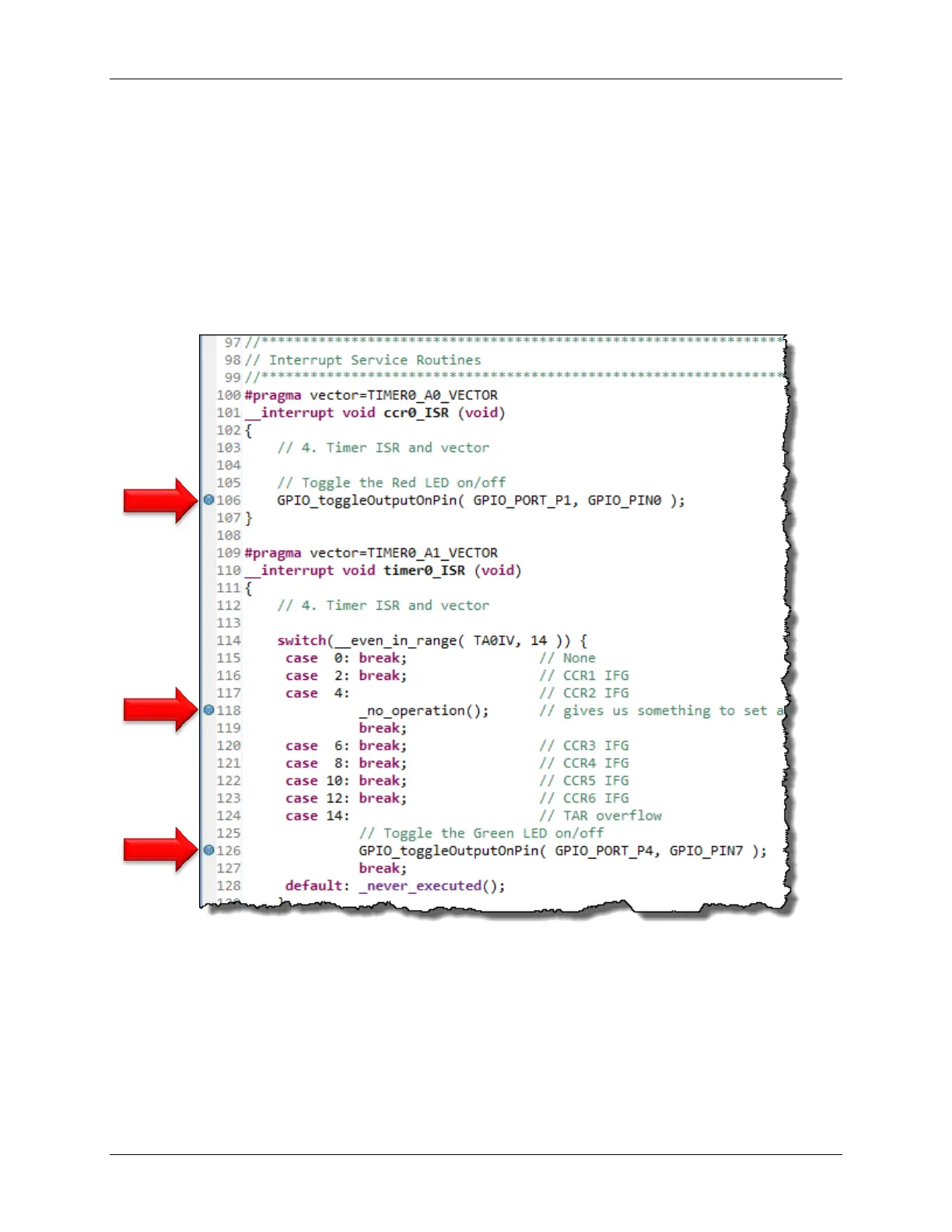
11. Launch the debugger and set three breakpoints inside the two ISR’s.
• When we run the code, the first breakpoint will indicate if we received the CCR0 interrupt.
If we wrote the code properly, we should NOT stop here.
• We should NOT stop at the second breakpoint either. CCR2 was setup to change the
Output Signal, not generate an interrupt.
• We should stop at the 3
rd
breakpoint. We left the timer configured to break whenever TAR
rolled-over to zero. (That is, whenever TA0IFG is set.)
12. Remove the breakpoints and let the code run. Do both LED’s toggle?
Why doesn’t the Red LED toggle? _____________________________________________
6 - 56 MSP430 Workshop - Timers