Trango Systems, Inc. GigaPlus User Manual Rev 3.1 20
Ports and Indicators – Indoor Unit
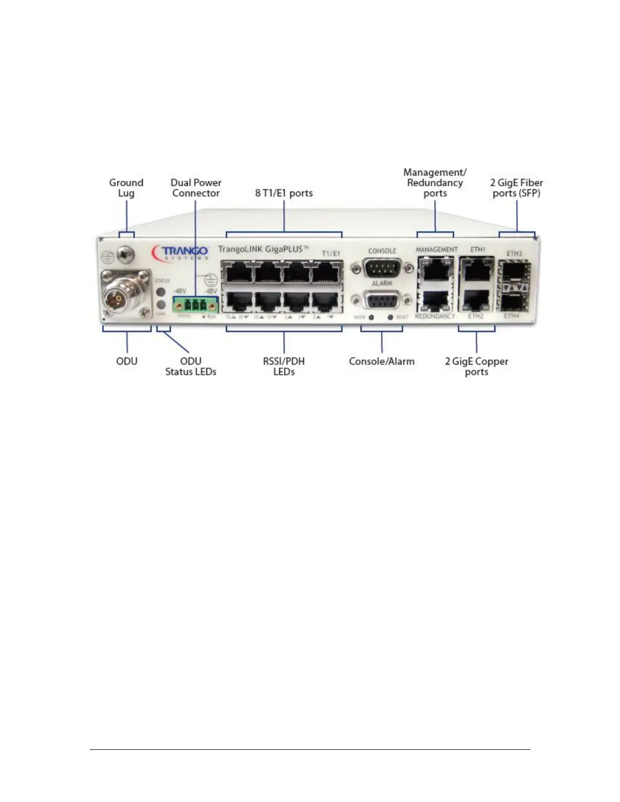
The Figure below shows the various ports on the GigaPlus IDU.
Figure 3 Front Panel of GigaPlus IDU
The TrangoLINK™ GigaPLUS front panel interface is described below:
N-Type Connector (ODU): The N-Type Connector connects the IDU to the ODU through
coaxial cable. This port carries the transmit and receive IF frequencies, the ODU control
signal, and the -48 VDC power to the ODU on the center conductor. N-Male to N-Male
cable terminations are required and LMR400 is recommended for most installations.
Ground Lug: Allows for proper grounding of the chassis to the rack, which is earth
grounded.
ODU Status LEDs(2): Top LED provides ODU power/PLL lock status while the bottom
LED provides RF link status. If the top LED is amber, the ODU is not powered on, not
connected, or one of the Phase Locked Loops (PLLs) in the ODU is faulty. If the bottom
LED is amber, RF link is not established. If the link is established both LEDs will be green.
Dual Power Connector: This is a three pin pluggable terminal block. The IDU is powered
by a -48V power supply (not included). The GigaPlus IDU does support the use of two
power supplies for power redundancy.