Do you have a question about the Trango Systems TrangoLINK GigaPlus and is the answer not in the manual?
Details FCC standards including CFR47 Part 15 and Part 101.
Lists ETSI standards including EN 302 217, EN 301 489, and EN 60950-1.
Confirms compliance with EU Directive 2002/95/EC on hazardous substances.
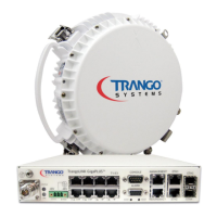
Describes the GigaPlus system as a high-performance split architecture point-to-point microwave system.
Details the front panel interface of the GigaPlus IDU, including connectors and LEDs.
Indicates where to find the serial number and MAC address on the IDU.
Illustrates and describes the ports and indicators on the GigaPlus HP ODU.
Explains the slip fit connection for ODUs and polarization change for 7-40 GHz models.
Discusses requirements for mounting ODUs with rectangular waveguide interfaces.
Describes how GigaPlus ODUs can be connected for 1+1 hot standby or aggregated capacity.
Details the recommended rack mount power supply for GigaPlus units.
Highlights flexible interfaces, form factor, and traffic capacity options.
Explains the system gain is due to LDPC FEC coding and its benefits.
Details supported frequency bands and T/R spacings for HP and HP2 ODUs.
Lists supported channel sizes and their corresponding Ethernet capacities.
Describes ACM for hitless modulation changes during weather fading.
Explains 1+1 hot standby functionality for protection against hardware failure.
Lists the supported channel bandwidths for the system.
Details the supported modulation levels: QAM256, QAM128, QAM64, QAM32, QAM16, QPSK.
Explains MSE as a measure of distortion and interference affecting link quality.
Describes ACM feature that shifts modulation based on MSE degrade thresholds.
Provides a table showing system capacity for each non-ACM speed setting.
Details ATPC for controlling remote side power output to achieve optimal signal strength.
Shows maximum transmitter power levels by band and modulation.
Lists minimum transmit power levels by band and ODU model.
Depicts maximum receiver RF level measured by RSSI.
Illustrates the typical setup of a GigaPlus in a ring architecture environment.
Explains the configuration of two GigaPlus units at each link end for hot standby.
Describes actions taken when a hardware failure triggers a failover event.
Details failover initiated by software based on specific conditions.
Explains manual failover initiated by user commands like 'utype_switch'.
Supports shutting down Ethernet ports to reroute traffic during link failure.
GigaPlus supports tagged packets with VLAN IDs for management traffic.
Explains Q in Q support and the function of smart_mode.
Describes QoS for prioritizing traffic types using VLAN COS or DSCP fields.
Allows assigning priority to untagged traffic on Ethernet ports.
Restricts ingress traffic rate on specific Ethernet ports for SLAs.
Fine-tunes QoS behavior for VLAN tagged traffic or port priority.
Outlines methods to manage and monitor GigaPlus link health and performance.
Describes access via Web Browser, including view and configuration levels.
Details access via SSH, Telnet, and Console ports.
Covers remote control and monitoring using SNMP with third-party NMS.
Specifies factory default IP addresses for units and IBM.
Lists default usernames and passwords for various access modes.
Provides steps to access the web interface and log in.
Explains the layout of the web interface navigation bar and its categories.
Introduces CLI for installation and troubleshooting, covering View, Config, Debug nodes.
Describes accessing and using the configuration node for system settings.
Details how to change view/debug and config node passwords.
Explains using the console port for CLI access when TCP/IP is unavailable.
Covers SNMP support for network management categories: Configuration, Accounting, Alarm, Monitoring.
Lists common SNMP objects for GigE bandwidth and RF monitoring.
Explains the process of updating IDU and ODU firmware files.
Step-by-step guide for performing firmware upgrades using TFTP.
Details the firmware upgrade process using FTP, noting its speed and error checking.
Explains how to upgrade system capacity using an alphanumeric key.
Describes the process of path analysis for minimal interference and reliability.
Emphasizes physical evaluation of proposed sites for Fresnel zone clearance and provisions.
Discusses spectrum licensing, typically on an individual path basis.
Covers general safety, equipment protrusions, laser hazards, and RF burns.
Outlines the standard procedure for installing the equipment.
Lists the required tools for installation.
Explains grounding of IF cable, antenna, ODU, and tower leg connections.
Details the installation of the -48 VDC rack mount power supply.
Covers coarse alignment using visual or third-party equipment.
Provides instructions for installing the IDU into a standard 19-inch rack.
Explains connecting the -48 VDC power supply to the GigaPlus unit.
Describes how to install the ferrite on the power cable to reduce noise.
Details the installation of a second standby unit in the rack.
Guides the installation of the HP ODU onto the antenna, including polarization.
Covers IF cable runs, lightning mitigation, and cable connectivity.
Explains proper sealing of antenna connections with Coax-Seal.
Describes ODU installation using a combiner for 1+1 hot standby.
Provides step-by-step guide for setting up a link via the web interface.
Explains the 1+1 setup process, extending the basic 1+0 configuration.
Enables ACM configuration of MSE Improve and Degrade thresholds.
Details ATPC configuration to maintain receive signal level during rain fading.
Allows enabling/disabling alarms, RPS, telnet, and tftp daemons from the web.
Enables, disables, and configures individual Ethernet traffic ports.
Configures QoS using Strict or Weighted Round Robin (WRR) modes.
Maps DSCP values to priority levels for WRR mode.
Describes methods to view traffic status and link health using web interface counters.
Displays radio and system status, including alarms, temperatures, and port connections.
Provides statistical information on front panel Ethernet ports for error rate and traffic flow.
Contains statistical information on each T1/E1 interface, updated every 20 seconds.
Shows summary statistics for RF in and RF out interfaces.
Covers IDU LED settings, Loopback Mode, Syslog level, and System Reboot.
Runs Linktest in digital and IF loopback modes automatically.
Helps diagnose link problems by displaying configuration, status comparison, and signal levels.
Records system events, errors, and statistics with time stamps.
Displays the current system configuration in ASCII format.
Allows setting view and config level access passwords for the web interface.
Allows setting system remark and changing web refresh rate.
Covers basic link setup using telnet, SSH, or serial COM port.
Recommends changing IP addresses on both ends before field installation.
Instructs to turn ODU power on and enter 'model' command.
Explains setting center frequency within model command limits.
Enables ACM using the 'acm enable' command on both link ends.
Sets payload speed, requiring a license key for speeds above 100 Mbps.
Instructs to turn 'opmode on' to enable transmitters.
Uses 'linktest' command to confirm link operation and check modulation levels.
Saves all settings to non-volatile FLASH memory using 'config save'.
Guides through configuring 1+1 hot standby using CLI commands.
Details antenna alignment using GPS compass, path analysis, and linktest command.
Covers changing IBM IP addresses to fit the application management network.
Explains activating traffic capacity licenses using the 'license' command.
Details ATPC configuration, including enabling and setting max power/step size.
Uses 'status port' command to show Ethernet statistics and RF counters.
Configures traps to notify external monitoring devices of threshold crossings.
Provides steps to resolve 'No Link' issues, checking frequencies and ODU installation.
Guides on troubleshooting high MSE or bit errors, checking transmitter power and target RSSI.
Addresses low RSSI issues, checking target RSSI setup and antenna alignment.
Helps diagnose packet loss when RF link is stable, checking Ethernet settings and cables.
Troubleshoots inability to connect via telnet or HTTP, checking cable connections.
Diagnoses issues with In-Band management connection.
Addresses problems with T1/E1 ports, checking configuration and license.
Explains key functions like Tab autocomplete, Del, Return, and arrow keys.
Describes node levels: View Node, Config Node, and Debug Node.
Lists commands available in the View Node for checking status.
Lists CLI commands and their default values for configuration.
Lists commands available in the Debug Node for system diagnostics.
Provides detailed syntax, description, and examples for individual CLI commands.
Provides physical specifications for IDU and ODU units.
Details operating and storage temperature, humidity, and water resistance.
Specifies compliance with ETSI and FCC conducted and radiated emissions standards.
States MTBF values for IDU and ODU units.
Lists EMC test methods and compliance with various EN standards.
Details wireless compliance with FCC, Canada, Europe, Australia, and New Zealand standards.
Lists system parameters like frequency range, channel sizes, and modulation levels.
Shows maximum transmit power by frequency and modulation.
Presents receive sensitivity values (dBm) across different channel widths and modulations.
Specifies failover time and guard time for 1+1 hot standby.
Details input voltage range and power consumption for IDU and ODU.
Lists Ethernet ports, OBM, T1/E1 ports, alarm inputs/outputs, and connectors.
Specifies packet size, max capacity, latency, QoS, and RSTP.
Details clock source, compliance, bit rate, impedance, and line code for T1/E1.
Shows pin-outs for straight-through and cross-over Ethernet cables (568A/B).
Illustrates cable pin-outs for T1/E1 cabling to RJ45 jacks.
Details DB9 console cable pin-outs and the console cable connector.
Provides pin-outs for the DB9 female alarm port on the IDU.
Lists HP ODU part numbers with frequency ranges and specifications.
Details Trango Microwave Band specific accessories for ODUs.
Form for recording customer, site name, address, coordinates, and access notes.
Checklist for antenna model, size, Fresnel zone, mounting, grounding, and weatherproofing.
Details ODU model, mounting, polarization, and condition.
Checks power supply type, redundancy, input voltage, and grounding.
Records cable type, length, and security of connections.
Fields for recording the installer's name, title, company, and date.
Fields for recording the approver's name, title, company, and date.
Log for recording Site A configuration details and personnel.
Details for Site A Unit #1: ODU/IDU model, serial, MAC, IP, polarization, settings.
Details for Site A Unit #2: ODU/IDU model, serial, MAC, IP, polarization, combiner.
Template for recording Site B customer, site name, address, and configuration.
Details for Site B Unit #1: ODU/IDU model, serial, MAC, IP, polarization, settings.
Details for Site B Unit #2: ODU/IDU model, serial, MAC, IP, polarization, combiner.
System Information.
1.544 Mbps telephony carrier 1.
Time-Division Multiplexing.
Threshold to Interference.
Trivial File Transfer Protocol.
Trivial File Transfer Protocol Daemon.
Transmit.
Virtual Local Area Network.
Wireless Internet Service Provider.
Weighted Round Robin.
| Brand | Trango Systems |
|---|---|
| Model | TrangoLINK GigaPlus |
| Category | Network Hardware |
| Language | English |